1. Understanding the Importance of Self-Checking Photoelectric Sensors
As an electrical engineer, you know that photoelectric sensors are critical in automation, from conveyor systems to packaging lines. A malfunction can halt production or cause safety risks. Self-checking ensures reliability, reducing downtime and maintenance costs. This video guide walks you through a systematic inspection process, focusing on key parameters like sensitivity, alignment, and electrical integrity.
2. Preliminary Safety and Setup
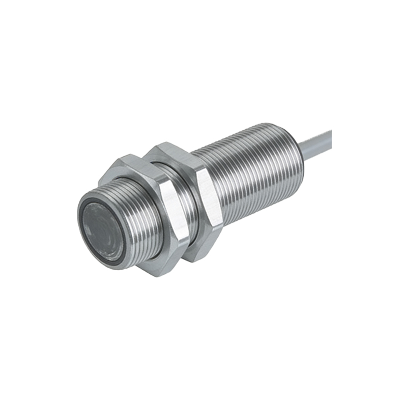
Before starting, power down the sensor circuit and verify no voltage is present using a multimeter. Wear insulated gloves and safety glasses. For the video, set up a test bench with a clean, stable mounting surface. Ensure the sensor’s lens is free from dust or debris—clean it with a lint-free cloth and isopropyl alcohol. Document the sensor’s model and specifications for reference.
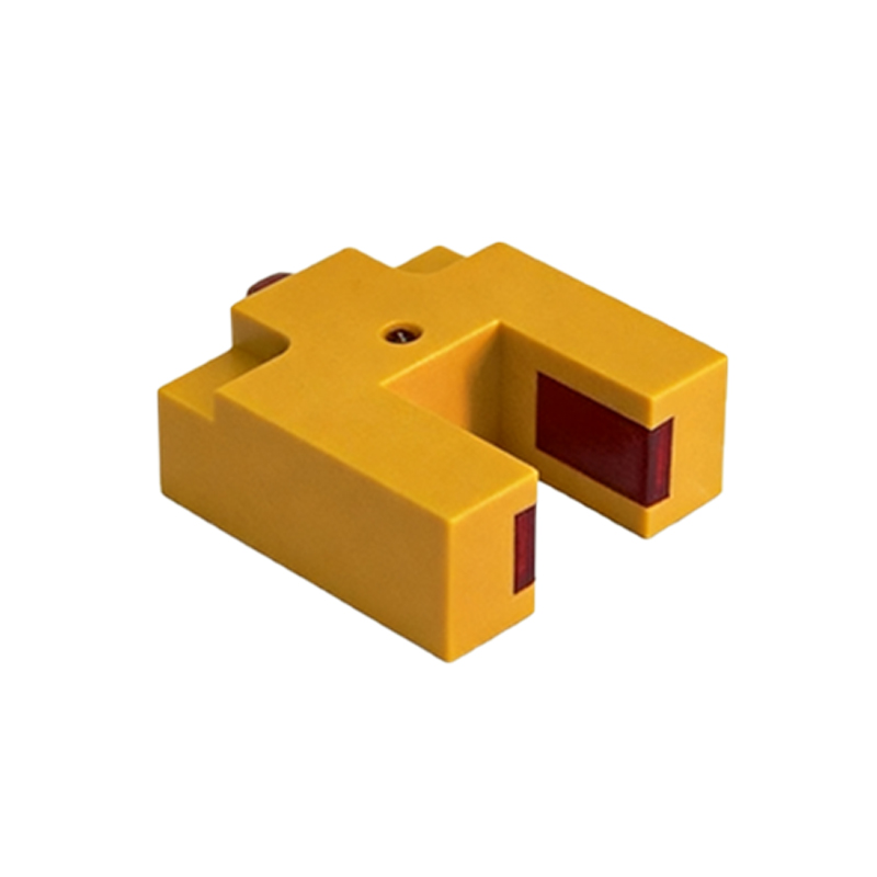
3. Visual Inspection of Physical Condition
Begin with a visual check. Examine the housing for cracks or corrosion, which can compromise seals. Look at the cable for cuts or fraying, common in high-vibration environments. Check the mounting bracket for looseness. In the video, zoom in on these areas to highlight signs of wear. Record any damage with a timestamp for your maintenance log.
4. Testing Sensor Response with a Target Object
Reapply power and configure the sensor to its standard operating mode. Use a target object (e.g., a metal plate for diffuse sensors or a reflector for retro-reflective types) to trigger the output. In slow motion, film the sensor’s LED indicator: it should switch states cleanly. Move the target at varying speeds to test dynamic response. If the output is erratic, adjust the sensitivity potentiometer or check for interference.
5. Verifying Alignment and Beam Integrity
For through-beam or retro-reflective sensors, alignment is crucial. Align the emitter and receiver with a laser alignment tool. In the video, show a test where you place an opaque object in the beam path—the output should toggle instantly. Measure the beam strength using a dedicated sensor analyzer tool if available. Misalignment often causes false triggers; correct it by adjusting mounting angles.
6. Electrical Validation with a Multimeter
Measure supply voltage at the sensor terminals—ensure it matches the rated range (e.g., 10-30V DC). Check the output signal (NPN/PNP) by connecting the sensor to a load resistor or PLC input. In the video, demonstrate how to read the voltage drop across the output: a healthy sensor shows near-zero in the active state and full supply in the inactive state. Watch for noise spikes on an oscilloscope.
7. Final Functional Test and Documentation
Run a complete cycle test: simulate 10-20 object passes and log the response times. Compare with manufacturer specifications. If all tests pass, reset the sensor to its original settings. In the video, conclude with a checklist for your maintenance log, including sensor ID, test date, and any adjustments made. This ensures traceability and aids predictive maintenance.