Understanding Photoelectric Sensor Basics
Photoelectric sensors are essential components in industrial automation, detecting objects through light emission and reception. They operate using a transmitter and receiver, with common types including through-beam, retro-reflective, and diffuse sensors. Before testing, verify the sensor's datasheet specifications, such as supply voltage (typically 10-30V DC), output type (NPN or PNP), and sensing range. Always use a regulated power supply to avoid voltage spikes, and ensure proper grounding to prevent electrical noise.
Essential Tools and Safety Precaution
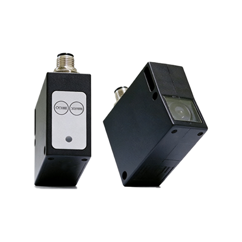
Gather a multimeter, oscilloscope (optional for signal analysis), screwdrivers, and wire strippers. Wear insulated gloves and safety glasses when working with live circuits. Disconnect power before making connections to avoid short circuits. Use a 24V DC power supply for most standard sensors, and confirm polarity: brown wire for VCC, blue for GND, black for output signal. For dual-output sensors, a white wire may indicate a second output.
Step-by-Step Wiring Procedure
First, strip 6-8 mm of insulation from each wire. Connect the brown wire to the positive terminal of the power supply and the blue wire to the negative terminal. For NPN sensors, connect the black output wire to a pull-up resistor (e.g., 10 kΩ) linked to VCC; for PNP sensors, connect it directly to the load, such as a PLC input module. Ensure the load is rated for the sensor's current capacity (usually up to 100 mA). Use a multimeter in continuity mode to check for open or short circuits.
Testing the Sensor Under Load
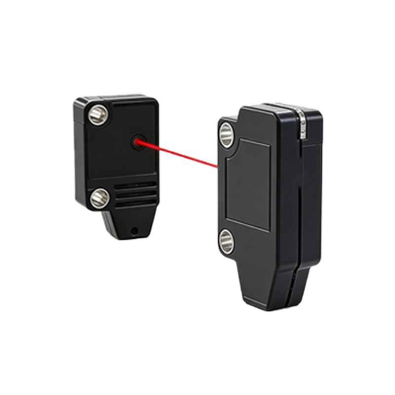
Reapply power and set the multimeter to DC voltage. Place the sensor in front of a target object (e.g., a white card for diffuse sensors). Measure the voltage between the black output and GND: it should switch from near 0V (dark state) to VCC (light state) for NPN sensors, or vice versa for PNP. For through-beam sensors, align the emitter and receiver precisely using a laser alignment tool. Note the response time (e.g., 1 ms) by observing the oscilloscope waveform.
Troubleshooting Common Issues
If the output remains constant, check for loose connections or incorrect polarity. Adjust the sensitivity potentiometer if available, especially in dusty environments. For retro-reflective sensors, ensure the reflector is clean and free of scratches. Use a shield cable for long runs (>10 meters) to minimize electromagnetic interference. Verify the ambient light level; direct sunlight can disrupt diffuse sensors, so install a hood or use modulated light sensors.
Final Verification and Maintenance
Perform a complete cycle test: move the target object multiple times and log the sensor's switching behavior. Record the test results for compliance with industry standards like IEC 60947-5-2. Periodically clean the sensor lens with a lint-free cloth and isopropyl alcohol. Replace any damaged cables or connectors promptly to maintain reliability in harsh environments.