Understanding the Photoelectric Sensor Basics
Photoelectric sensors are essential components in industrial automation, used to detect the presence, absence, or distance of objects using light. As an electrical engineer, programming these sensors requires a solid grasp of their operating principles: through-beam, retro-reflective, and diffuse modes. Each mode influences the programming logic, from sensitivity adjustments to output configuration. Before coding, always verify the sensor’s datasheet for voltage requirements (typically 10-30 VDC), output types (NPN or PNP), and response time. This foundational knowledge ensures efficient integration into PLC systems or microcontrollers.
Setting Up the Hardware and Wiring
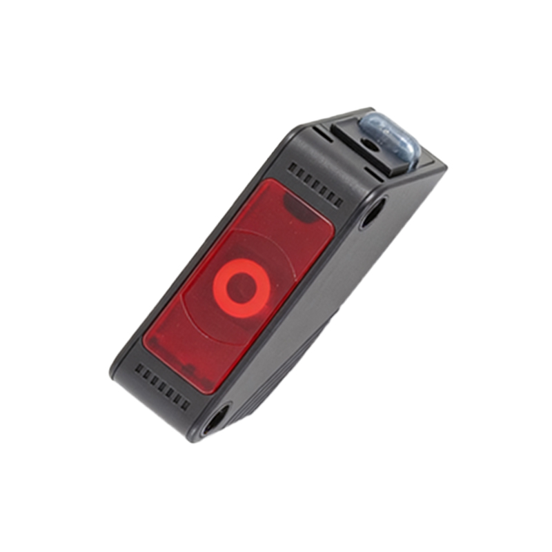
Begin by physically mounting the sensor at the correct distance from the target object, avoiding reflective surfaces that could cause false triggers. For through-beam sensors, align the emitter and receiver precisely. Wire the sensor to your controller—connect the brown wire to +24V DC, blue to ground, and the black output wire to a digital input pin on your PLC or microcontroller (e.g., Arduino or Siemens S7-1200). Use a pull-up resistor for NPN outputs or a pull-down resistor for PNP outputs to stabilize the signal. Double-check connections with a multimeter to prevent short circuits or voltage drops.
Writing the Initialization Code
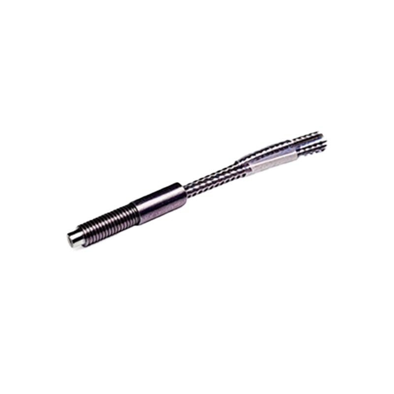
In your programming environment, define the input pin for the sensor. For example, in ladder logic for a PLC, create a normally open contact for the sensor input. In C++ for an Arduino, usepinMode(sensorPin, INPUT); in the setup function. Set a debounce delay (e.g., 10 ms) to filter out noise from flickering light or vibrations. Initialize a variable to store the sensor state, such asbool sensorState = false;. This step ensures the sensor responds only to stable detections, avoiding false readings in noisy industrial environments.
Implementing Detection Logic and Output Control
In the main loop, read the sensor input usingdigitalRead(sensorPin); for simple on/off detection. For analog sensors, useanalogRead() to measure light intensity, then compare it to a threshold value. Program conditional statements to trigger outputs: if the sensor detects an object (e.g., LOW for NPN, HIGH for PNP), set an output pin to activate a relay or conveyor motor. In ladder logic, use a timer to delay the output for precise timing, such as holding a product for labeling. Test with a known object to calibrate sensitivity, adjusting the potentiometer on the sensor if needed.
Debugging and Optimizing Performance
After coding, monitor the sensor’s behavior using serial communication (e.g.,Serial.println(sensorState);) or PLC diagnostic tools. Common issues include ambient light interference—apply a shield or reduce gain via the sensor’s adjustment screw. For fast-moving objects, increase the sensor’s response frequency (e.g., 1 kHz) in code by using hardware interrupts instead of polling. Log data to identify false triggers, then refine threshold values or add hysteresis (e.g., 5% margin). Finally, document the program with comments for maintenance, ensuring compliance with industry standards like IEC 61131-3.