Introduction to Slot-Type Photoelectric Sensors
Slot-type photoelectric sensors, also known as fork sensors, are widely used in industrial automation for detecting objects, counting components, or controlling machinery. They consist of an emitter and receiver housed in a single slot-shaped unit, making them ideal for precise detection in confined spaces. A critical aspect of these sensors is the output configuration, typically either NPN (sinking) or PNP (sourcing). Understanding the difference is essential for correct integration into control systems.
What is NPN Output in Slot-Type Sensors?
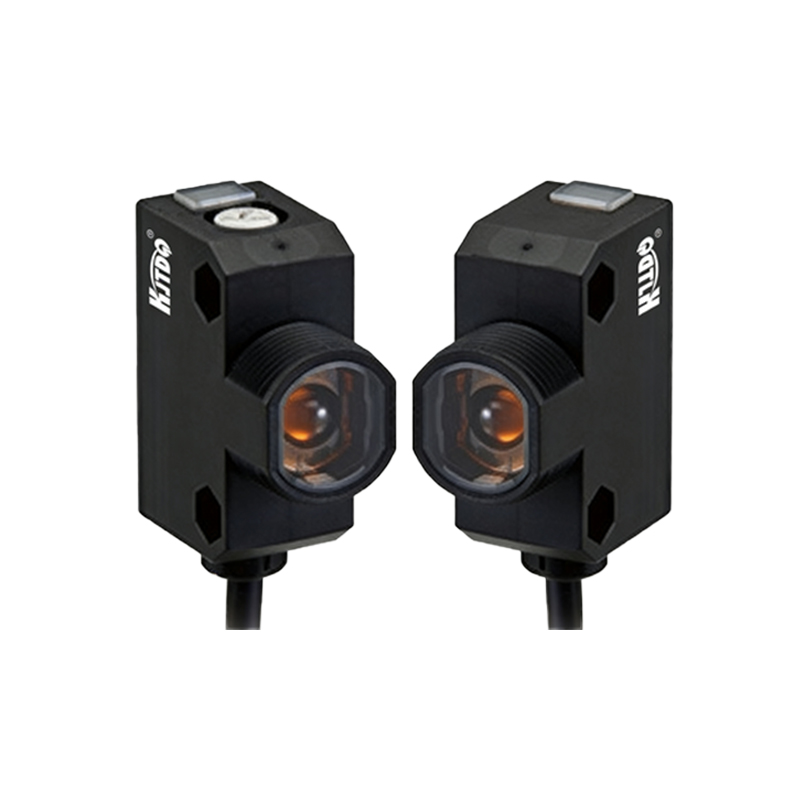
NPN output, commonly referred to as "sinking" output, means the sensor’s output transistor connects the load to ground (0V) when activated. In a typical NPN configuration, the load is connected between the positive power supply (VCC) and the sensor output. When the sensor detects an object, the output transistor turns on, allowing current to flow from VCC, through the load, to ground. This is standard in many Asian and Japanese industrial systems, where the controller input is often designed to accept sinking signals.
What is PNP Output in Slot-Type Sensors?
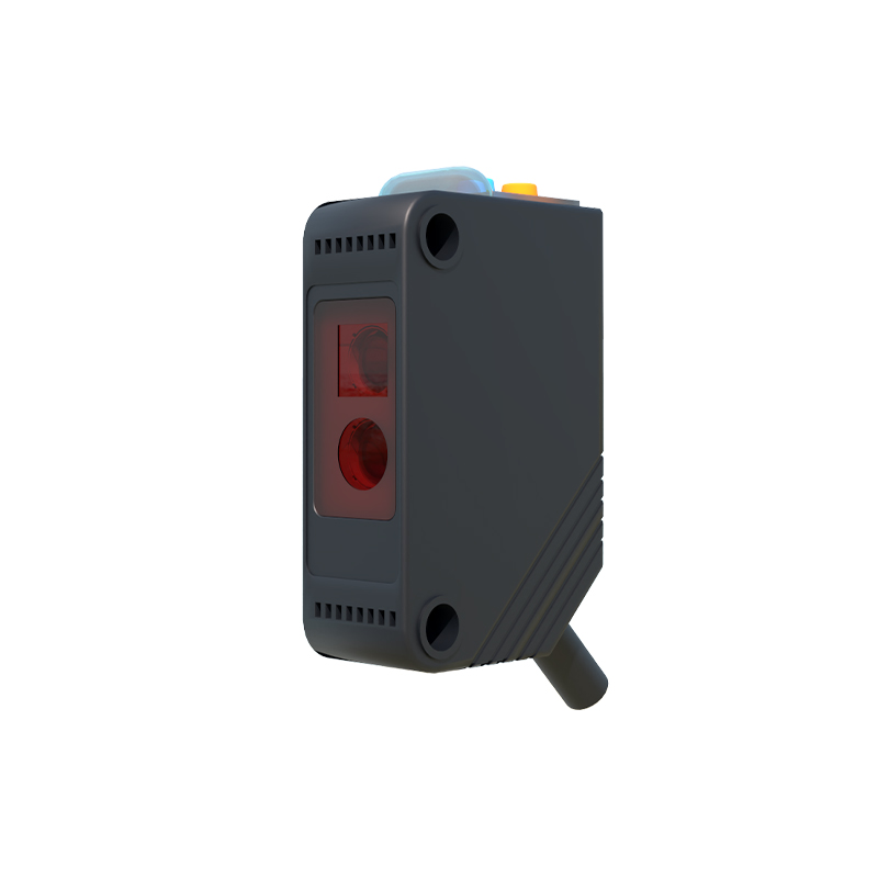
PNP output, or "sourcing" output, operates differently. Here, the output transistor connects the load to the positive power supply (VCC) when activated. The load is connected between the sensor output and ground (0V). When the sensor detects an object, the transistor turns on, supplying positive voltage to the load. PNP outputs are prevalent in European and North American industrial applications, where controller inputs are typically sourcing.
Key Electrical Differences
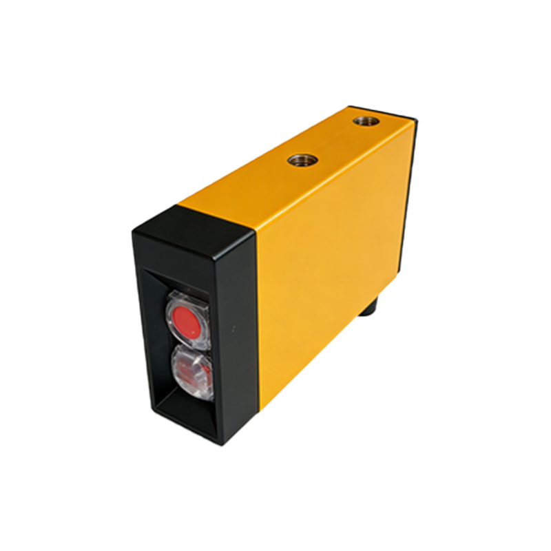
The fundamental difference lies in how the output transistor handles current flow:
- NPN: Transistor is connected between output and ground. Active state: output is LOW (close to 0V). Load is between VCC and output.
- PNP: Transistor is connected between output and VCC. Active state: output is HIGH (close to VCC). Load is between output and ground.
This affects wiring, voltage levels, and compatibility with PLCs or other controllers. For example, using an NPN sensor with a PNP-only input requires a conversion circuit.
Application Considerations
Choice depends on system design. NPN sensors are common in cost-sensitive or battery-powered devices due to lower power consumption in some configurations. PNP sensors are often preferred for safety because a short circuit to ground (common in industrial settings) does not falsely trigger the output. Additionally, many modern PLCs offer selectable input types, but legacy systems may strictly require one type. Always verify the sensor’s datasheet for output type, load current, and voltage ratings.
Wiring and Troubleshooting Tips
When wiring a slot-type sensor:
- Check the sensor’s label: NPN or PNP is usually marked as "NPN NO" (normally open) or "PNP NC" (normally closed).
- Use a multimeter to measure output voltage: Active NPN output shows near 0V; active PNP shows near VCC.
- Ensure the load (e.g., relay, PLC input) matches the sensor output type. Mismatch can damage components or cause erratic operation.
- For mixed systems, use a converter module or optocoupler to bridge NPN and PNP signals.