Understanding the Basics of Photoelectric Sensor Installation
Photoelectric sensors are essential components in industrial automation, used for detecting objects without physical contact. Proper installation ensures reliable performance and longevity. As an electrical engineer, you must first select the correct sensor type—through-beam, retro-reflective, or diffuse—based on the application. Through-beam sensors offer the longest range but require alignment of separate emitter and receiver units. Retro-reflective sensors combine emitter and receiver in one housing, using a reflector for detection. Diffuse sensors detect reflected light from the target itself, ideal for short-range applications. Always verify the sensor’s operating voltage, output type (NPN or PNP), and environmental ratings (e.g., IP67 for dusty or wet areas).
Preparing the Mounting Location and Power Supply
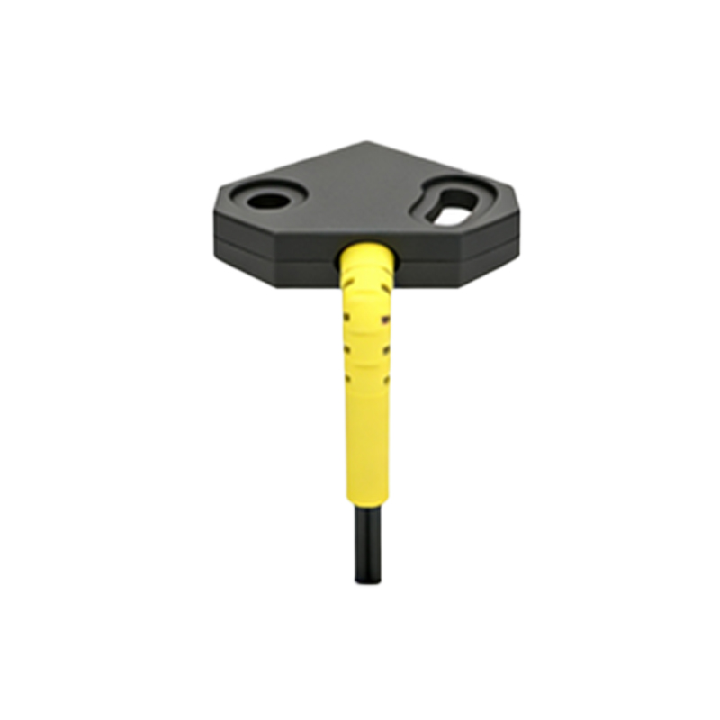
Before installation, inspect the mounting surface to ensure it is stable, vibration-free, and free from obstructions. Use stainless steel brackets or adjustable mounts to secure the sensor, as they resist corrosion and allow fine-tuning of alignment. For power supply, connect the sensor to a regulated DC source (typically 10-30V DC) to avoid voltage spikes that can damage electronics. Use shielded cables for long runs to minimize electromagnetic interference (EMI). Strip wires carefully, and twist shielded drains to ground at the controller side only. For through-beam sensors, position the emitter and receiver facing each other with a clear line of sight, ensuring the beam is unobstructed by dust or debris.
Aligning Through-Beam Sensors for Optimal Performance
Through-beam sensors require precise alignment to function correctly. Mount the emitter and receiver on stable supports, parallel to each other. Use a laser alignment tool or a simple sighting method to ensure the beam hits the receiver’s center within a 2-degree tolerance. Power both units, and adjust their positions while monitoring the output signal indicator. A steady green LED indicates proper alignment. Secure all bolts, and test with a target moving across the beam path. If the sensor fails to detect, check for dirty lenses or misalignment caused by thermal expansion of mounts. In high-vibration environments, add lock washers or thread-locking compound to prevent loosening.
Setting Up Retro-Reflective Sensors with Proper Reflector Placement
For retro-reflective sensors, mount the sensor on a flat surface, aiming it at a reflector placed at the specified distance (typically 0.1 to 10 meters). The reflector must be perpendicular to the sensor lens to reflect the beam back accurately. Avoid shiny objects or shiny backgrounds near the reflector, as they can cause false detections. Adjust the sensor’s sensitivity potentiometer if necessary to filter out background noise. Verify the beam’s path is clear of dust or oil on the reflector. Test by placing a non-reflective target between the sensor and reflector; the output should immediately switch. Use a polarizing filter to handle highly reflective targets.
Installing Diffuse Sensors for Short-Range Detection
Diffuse sensors are easier to install but require careful consideration of the target’s reflectivity. Mount the sensor perpendicular to the target’s surface, at a distance specified in the datasheet (e.g., 10 to 300 mm). The target color and material significantly affect detection range—white or bright objects reflect more light, increasing range, while dark or matte surfaces reduce it. Calibrate the sensor using a sample of the actual target to set the threshold. Avoid installing near highly reflective walls or metal surfaces that may cause stray reflections. Use a background suppression model if the background is too close to the sensor.
Wiring and Testing Connections for Reliable Operation
After physical mounting, wire the sensor according to its diagram: brown wire to V+, blue to V-, and black (output) to the PLC input. For PNP sensors, the output switches positive voltage; for NPN, it switches ground. Double-check polarity to prevent short circuits. Use a multimeter to verify voltage at the sensor terminals (should be within ±10% of rated value). Test the sensor by moving a target through the detection zone, observing the LED indicator for consistent response. Record the switching frequency and response time—if below spec, check for cable length issues (over 100 meters may require a signal booster).
Final Inspection and Troubleshooting Common Issues
Conduct a final inspection: ensure all connections are tight, no exposed wires, and the sensor is free from chemical or thermal hazards. Common problems include intermittent detection due to dirty lenses—clean with isopropyl alcohol and a lint-free cloth. If the sensor fails to respond, test with a known-good sensor to isolate the fault. For false triggers, adjust the sensitivity or add a delay filter. Document the installation parameters for future maintenance. Remember to comply with local electrical codes and safety standards, such as NEC for wire gauges and grounding.