Understanding the Root Causes of Interference in Photoelectric Sensors
Interference in photoelectric sensors often stems from external light sources, electrical noise, or environmental factors. For instance, ambient light from sunlight or high-intensity discharge lamps can saturate the receiver, causing false triggers. Electrical noise from nearby motors, inverters, or switching power supplies induces voltage spikes on the sensor's signal lines. Additionally, reflective surfaces or dust accumulation on the lens can scatter the emitted beam, leading to erratic readings. As an engineer, always verify the sensor's operating wavelength and filter settings to reject unwanted light. Shielded cables and proper grounding are essential to mitigate electromagnetic interference (EMI).
Diagnosing Jitter in Sensor Output Signals
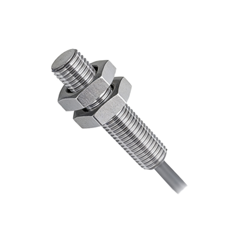
Jitter, or rapid fluctuations in the sensor's output, often indicates instability in the detection threshold. This can occur when the target object is moving at high speed, causing partial beam interruption. Vibrations from machinery or loose mounting brackets also introduce mechanical jitter. To diagnose, use an oscilloscope to analyze the output waveform. Look for inconsistent pulse widths or multiple transitions within a single cycle. Adjust the sensor's response time or hysteresis settings to filter out noise. If jitter persists, consider upgrading to a sensor with a faster response frequency or a background suppression feature.
Practical Solutions for Reducing Electrical Interference
To combat electrical interference, start by isolating sensor cables from high-voltage power lines. Use twisted-pair cables with foil shielding and ensure the shield is grounded at one end only to avoid ground loops. Install ferrite beads or line filters on the power supply to suppress high-frequency noise. In severe cases, employ a dedicated DC power source for sensors, separate from motor drives. Also, verify that the sensor's output type (PNP, NPN, or push-pull) matches the PLC input module to prevent signal mismatch.
Optimizing Sensor Placement and Environmental Control
Physical placement plays a critical role in performance. Avoid aiming the sensor directly at reflective metals or glossy surfaces, which can cause false echoes. Use a retro-reflective sensor with a polarized lens to reject stray reflections. For dusty or humid environments, install an air purge system or choose sensors with IP67 or higher ratings. Regularly clean the lens with a lint-free cloth and isopropyl alcohol. If the sensor is exposed to strong ambient light, add a sunshade or adjust the sensitivity to a narrower detection window.
Advanced Techniques: Synchronization and Redundancy
In multi-sensor systems, cross-talk between adjacent units can mimic interference. Synchronize sensors by using a common clock signal or staggering their emission cycles. Alternatively, employ sensors with different light frequencies (e.g., infrared vs. red LED). For critical applications, implement redundant sensor arrays with voting logic to override false signals. Always document the installation parameters, including beam angle, sensing distance, and response time, for future troubleshooting.
Final Checklist for Reliable Sensor Operation
After implementing these fixes, validate the system under all operating conditions. Monitor the signal-to-noise ratio (SNR) using a data logger. Ensure the sensor's load current does not exceed its rating to prevent thermal drift. If the issue persists, consult the manufacturer's application notes or consider a fiber optic sensor for harsh environments. Remember, systematic testing and incremental adjustments are key to eliminating interference and jitter.