Introduction to Photoelectric Sensor Tachometers
A photoelectric sensor tachometer is an essential instrument used in industrial automation and mechanical engineering to measure the rotational speed of shafts, motors, and other rotating components. By utilizing optical principles, it provides non-contact, high-precision RPM (revolutions per minute) readings. The core of this device lies in its schematic diagram, which integrates a light emitter, a photodetector, signal conditioning circuitry, and a display or output module. This article delves into the key components and signal flow within a typical photoelectric tachometer schematic.
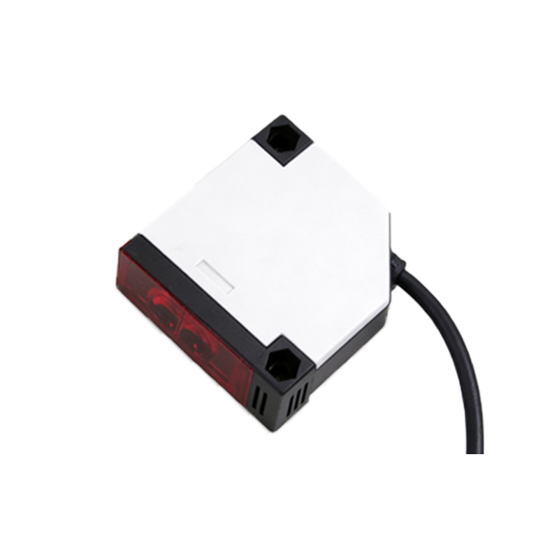
Basic Operating Principle
The tachometer operates by projecting a beam of light onto a rotating target, which often has reflective or non-reflective markings (e.g., a single reflective strip on a black shaft). As the target rotates, the reflected light pulses are captured by the photodetector. Each pulse corresponds to one complete rotation. The schematic must convert these optical pulses into electrical signals, which are then processed to calculate RPM. The fundamental equation is: RPM = (Number of pulses per minute) / (Number of pulses per revolution). For a single mark, this simplifies to RPM = pulse frequency × 60.
Key Components in the Schematic Diagram
The typical schematic diagram of a photoelectric sensor tachometer includes several critical components:
- Light Source: Usually an infrared LED (Light Emitting Diode) with a narrow beam angle, driven by a constant current source to ensure stable illumination.
- Photodetector: A phototransistor or photodiode that converts reflected light into a small current. It is often paired with an ambient light shield to reduce noise.
- Transimpedance Amplifier: Converts the photodetector’s current output into a voltage signal. This stage uses an operational amplifier (op-amp) with a feedback resistor to achieve high gain.
- Comparator Circuit: A Schmitt trigger or voltage comparator shapes the analog voltage pulses into clean digital square waves. This eliminates noise and ensures reliable pulse detection.
- Microcontroller or Frequency-to-Voltage Converter: Processes the digital pulses. A microcontroller calculates RPM using internal timers, while an analog circuit may use a PLL (Phase-Locked Loop) or F/V converter.
- Output Stage: Drives a display (LCD or 7-segment LED) or provides an analog voltage output (0-10V or 4-20mA) for PLC integration.
Signal Flow and Processing
The signal flow begins with the photodetector generating a weak, noisy signal. The transimpedance amplifier boosts this to a few volts. The comparator then cleans the signal, producing a square wave with a frequency proportional to the rotational speed. In a digital design, the microcontroller measures the time between rising edges (period measurement) or counts pulses over a fixed gate time (frequency measurement). High-speed applications often use a period measurement method for better accuracy, while low-speed applications favor frequency counting. The final RPM value is then sent to the display or output port.
Practical Considerations in Circuit Design
Engineers must address several factors when implementing this schematic. First, the optical path must be aligned precisely to avoid false triggers. Second, the photodetector’s response time should match the maximum expected RPM. For example, at 10,000 RPM with one mark, the pulse frequency is 166.7 Hz, requiring a photodetector with a rise time under 1 ms. Third, electromagnetic interference (EMI) from nearby motors can corrupt signals; thus, shielded cables and bypass capacitors on the power supply lines are essential. Finally, calibration is critical: the schematic should include a trim potentiometer to adjust the comparator threshold or gain to account for variations in reflectivity and distance.
Typical Schematic Example and Interpretation
A standard schematic might show an IR LED (D1) connected to a current-limiting resistor (R1) and a transistor driver (Q1) for modulation (optional). The phototransistor (Q2) is biased with a pull-up resistor (R2) and connected to the non-inverting input of an LM358 op-amp configured as a transimpedance amplifier (Rf = 100kΩ). The output feeds into a comparator (LM393) with hysteresis set by R3 and R4. The comparator’s output goes to a microcontroller input pin (e.g., Arduino or PIC). The microcontroller’s timer captures the pulse width, and the software computes RPM. This design is cost-effective and widely used in DIY and industrial tachometers.