Understanding Signal Degradation in Long Cable Runs
In photoelectric sensor systems, extending cable length beyond the standard 2 meters requires careful consideration of signal integrity. As cable length increases, voltage drop and capacitance become critical factors, especially for DC-powered sensors. For instance, a 24V DC sensor operating at 100mA may experience a voltage drop of up to 1.2V per 10 meters of 22AWG cable. This can trigger false triggers or sensor failures. Engineers must calculate the total load current and cable resistance to ensure the sensor receives minimum operating voltage, typically 10-30V DC for industrial models. Additionally, high capacitance in long cables can slow response times and distort pulse signals, particularly in high-speed detection applications. Using twisted-pair shielded cables mitigates electromagnetic interference (EMI) but increases capacitance; thus, balancing shielding and capacitance is crucial.
Selecting the Right Cable Type and Gauge
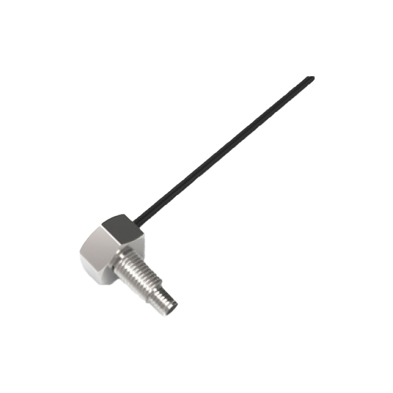
For cable extensions, wire gauge (AWG) directly impacts performance. Thicker wires (e.g., 18AWG) reduce resistance and voltage drop but may be less flexible. In contrast, 22AWG or 24AWG is common for short extensions but risks voltage loss over 15 meters. For sensor cables exceeding 10 meters, 16AWG or 14AWG is recommended to maintain power stability. Shielded cables (e.g., Belden 8777) are essential in electrically noisy environments, while unshielded options suffice for clean installations. Additionally, consider cable jacket materials: PVC for general use, PUR for oil and abrasion resistance, and TPE for extreme temperatures. Always match the cable's temperature rating to the environment to avoid insulation breakdown.
Using Signal Amplifiers and Repeaters
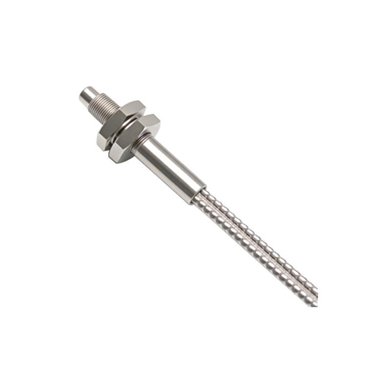
When cable lengths exceed 30 meters or sensor output voltage drops below threshold levels, integrating signal amplifiers or repeaters becomes necessary. These devices boost the sensor signal to restore full pulse amplitude and edge sharpness. For example, a Photoelectric Sensor Repeater Module (e.g., Banner D12SP6Y) can extend cable length up to 100 meters by regenerating the signal. Amplifiers require separate power supply and should be positioned near the sensor to minimize noise pickup. Alternatively, use sensors with built-in adjustable gain to compensate for moderate losses. For fiber optic sensors, signal repeaters are often integrated into the amplifier unit.
Employing Remote I/O Modules for Distributed Architecture
In large-scale systems, replacing long sensor cables with remote I/O modules (e.g., IO-Link masters, EtherCAT couplers) offers a robust solution. These modules convert sensor signals to digital communication protocols (e.g., IO-Link, Profibus) and transmit over twisted-pair Ethernet or fiber optic cables, achieving distances over 100 meters without degradation. This approach reduces cable weight, simplifies troubleshooting, and enables advanced diagnostics. For instance, an IO-Link master with M12 connectors can handle up to 16 sensors per module. Engineers must ensure the module's power budget accommodates all connected sensors.
Testing and Validation Protocols
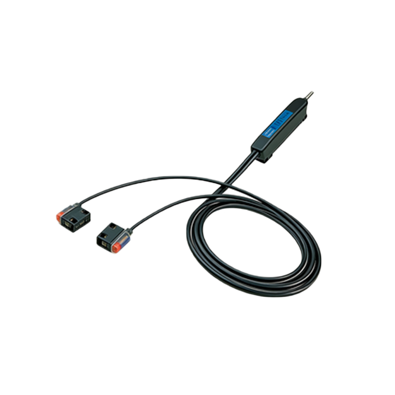
After installation, perform comprehensive tests to verify performance. Use an oscilloscope to measure signal rise/fall times at the controller end; a 10% increase in rise time beyond sensor specifications indicates excessive capacitance. Measure voltage at the sensor under full load with a multimeter; if below 10V for a 24V sensor, adjust power supply or cable. Conduct a 24-hour run with simulated target detection to catch intermittent failures. For critical applications, consider using cable length compensation circuits or pre-terminated cable assemblies with factory-tested performance. Document all measurements and cable specifications for future maintenance.