Understanding the Operating Principle of Photoelectric Sensors
Photoelectric sensors are primarily designed for detecting objects, distances, and light variations, not for direct voltage measurement. However, with appropriate auxiliary circuits, they can be adapted for voltage sensing. The key lies in converting voltage into a variable that affects light intensity, such as LED brightness or phototransistor current. In industrial applications, this is achieved by integrating a voltage-to-light converter, such as an optocoupler or a voltage-controlled light source, allowing the sensor to indirectly measure voltage levels.
Selecting the Right Photoelectric Sensor for Voltage Measurement
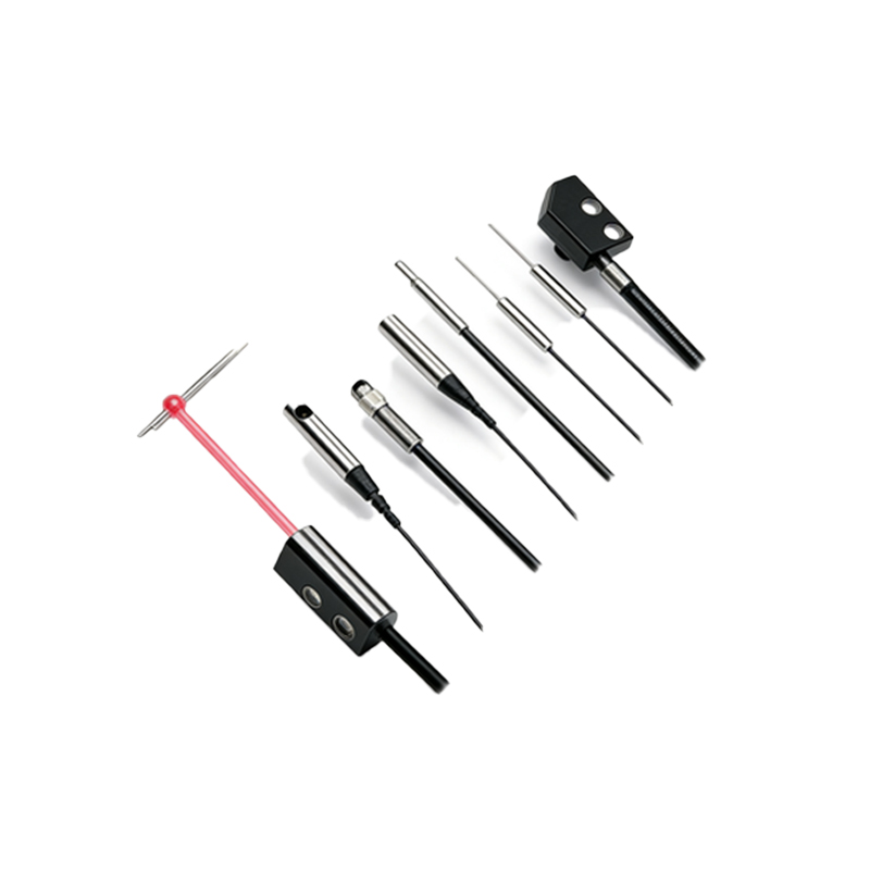
Not all photoelectric sensors are suitable for this task. For voltage measurement, engineers should choose sensors with high linearity and fast response times, such as through-beam or retro-reflective types. These sensors offer stable light output and minimal hysteresis. Additionally, the sensor must operate within a specified wavelength range compatible with the light source used. For example, an infrared sensor paired with an infrared LED voltage modulator provides reliable and accurate readings, especially in noisy industrial environments.
Designing the Voltage-to-Light Interface Circuit
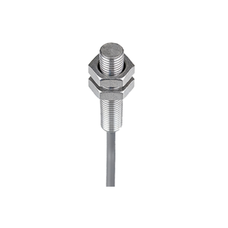
The core of this method is the interface circuit that converts voltage into light intensity. A common approach uses a voltage-controlled current source driving an LED. The LED's brightness varies proportionally with the input voltage, which is then detected by the photoelectric sensor. To ensure precision, incorporate a linearization circuit, such as an operational amplifier with feedback, to compensate for LED nonlinearity. Calibration resistors and capacitors should be chosen to match the desired voltage range, typically 0-10V or 4-20mA signals.
Calibrating the System for Accurate Voltage Readings
Calibration is essential to map light intensity to voltage values. Begin by applying known reference voltages (e.g., 0V, 5V, 10V) and recording the sensor's output, usually in milliamps or volts. Use a regression analysis to establish a linear equation between input voltage and sensor output. Environmental factors like ambient light and temperature drift must be compensated. Implement a feedback loop with a reference light source to stabilize readings over time, ensuring long-term accuracy.
Integrating the Sensor into an Industrial Control System
Once calibrated, the sensor can be connected to a PLC or data acquisition system via analog input modules. Use shielded twisted-pair cables to minimize electromagnetic interference. For digital output, add an analog-to-digital converter (ADC) with appropriate resolution, typically 12-bit or 16-bit, to capture fine voltage variations. In automated settings, include a software filter to remove noise spikes, ensuring stable voltage monitoring in real-time applications like motor drives or power supplies.
Troubleshooting Common Issues in Voltage Measurement
Common problems include nonlinearity due to LED aging, drift from temperature changes, and signal noise from power lines. To mitigate LED aging, use a constant current source with automatic brightness compensation. For temperature drift, incorporate a thermistor in the feedback loop or use a temperature-compensated LED. Noise issues can be resolved by adding a low-pass filter at the sensor output and ensuring proper grounding of the interface circuit. Regular recalibration every 6 months maintains accuracy.
Safety and Operational Considerations
When measuring high voltages (above 50V), implement galvanic isolation using optocouplers to protect the sensor and control system. Use appropriate fuses and surge protection devices. Ensure the sensor's housing is rated for the industrial environment, such as IP67 for dust and moisture. Always follow local electrical codes and use test leads with proper insulation. Document all calibration data and maintenance logs for compliance and traceability.