Understanding Background Suppression Photoelectric Sensors
Background suppression photoelectric sensors are essential components in industrial automation, designed to detect objects within a specific range while ignoring backgrounds beyond that set point. Unlike diffuse sensors that rely on reflectivity, these sensors use triangulation or time-of-flight principles to accurately measure distance. This ensures reliable detection even on shiny or dark surfaces. Engineers must understand the wiring protocol to avoid signal interference and false triggers.
Identifying Sensor Wiring Terminals
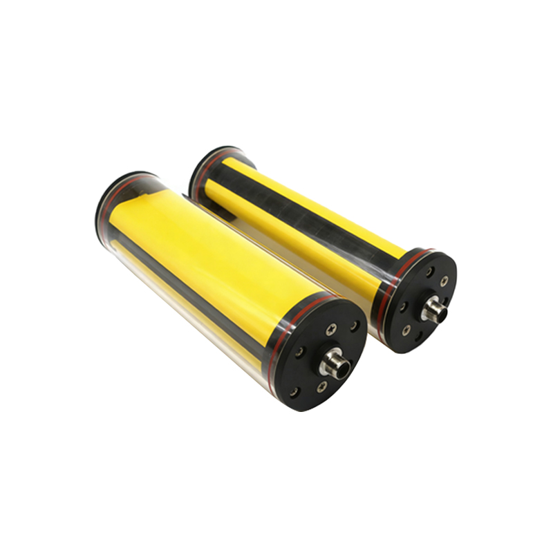
Before connecting, examine the sensor's datasheet for terminal identification. Most background suppression sensors have four wires: brown (VCC, typically 10-30V DC), blue (GND), black (normally open output, NO), and white (normally closed output, NC). For models with IO-Link, additional communication wires may exist. Use a multimeter to verify continuity if labels are unclear. Proper identification prevents reverse polarity damage.
Power Supply Connection
Connect the brown wire to the positive terminal of your DC power supply, ensuring voltage matches sensor specifications (e.g., 24V DC). The blue wire connects to the system ground. Use a regulated power source to minimize ripple voltage, which can cause erratic sensor behavior. For long cable runs (over 10 meters), consider a shielded cable to reduce electromagnetic interference. Secure connections with terminal blocks or soldering, and apply heat shrink tubing for insulation.
Output Wiring for PLC Integration
The black wire (NO output) connects to a digital input of your PLC or controller. When the sensor detects an object within the set range, this output switches to high state (typically +VCC). The white wire (NC output) is often used for fault detection or safety circuits. For sinking (NPN) sensors, outputs switch to GND when active; for sourcing (PNP) sensors, outputs switch to VCC. Confirm sensor type using the datasheet. Add a pull-up or pull-down resistor (e.g., 10kΩ) if the PLC input lacks internal biasing.
Setting the Background Suppression Distance
After wiring, calibrate the sensor using its potentiometer or digital interface. Place a target at the desired detection distance and adjust the background suppression threshold until the sensor triggers reliably. For sensors with IO-Link, use a software tool to set the cutoff distance and hysteresis. Test with background materials (e.g., dark metal or reflective plastic) to ensure no false readings. Lock the adjustment screw to prevent drift.
Testing and Troubleshooting Common Issues
Power the system and use a multimeter to check voltage between brown and blue terminals (should match VCC). Verify output switching by moving a test object in front of the sensor. If the output doesn't change, check for loose connections or incorrect wiring polarity. For false triggering, reduce the sensitivity or increase the background suppression distance. Ensure cable shielding is grounded at one end to prevent noise loops. Document all settings for future maintenance.
Final Verification and Safety Checks
After installation, run a full cycle test with the production line. Monitor sensor response time (typically<1 ms) using an oscilloscope if needed. Confirm that the sensor's LED indicator (usually green for power, yellow for detection) behaves as expected. Insulate all exposed wires with electrical tape and secure cables along the machine frame to avoid snagging. Follow local electrical codes and lockout/tagout procedures during maintenance.