Understanding the Basics of Photoelectric Sensors and Pneumatic Cylinders
In industrial automation, integrating a photoelectric sensor with a pneumatic cylinder is a common task for precise position detection, object counting, or safety interlocking. A photoelectric sensor emits a light beam (infrared or visible) and detects changes in the reflected or interrupted light. A pneumatic cylinder uses compressed air to create linear motion. The goal is to use the sensor’s output signal to control the cylinder’s stroke, such as extending or retracting when an object is detected. Ensure the sensor type (through-beam, retro-reflective, or diffuse) matches your application. For example, a through-beam sensor offers long-range detection but requires separate emitter and receiver, while a diffuse sensor simplifies wiring by combining both in one unit.
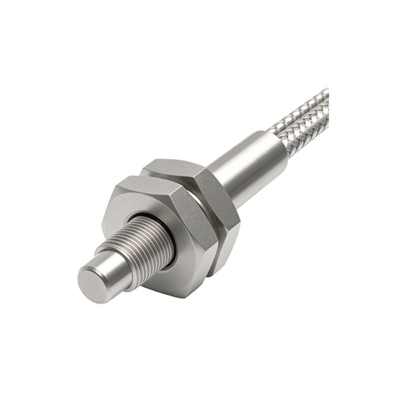
Required Components and Tools
Before starting, gather the following: a photoelectric sensor (e.g., PNP or NPN output type), a pneumatic cylinder with solenoid valve (typically 24V DC), a programmable logic controller (PLC) or relay, power supply (24V DC), wires, screwdrivers, multimeter, and cable connectors. Confirm the sensor’s output logic: PNP sensors source current (positive switching) to the load, while NPN sensors sink current (negative switching). For most PLC inputs, PNP is preferred as it matches standard positive logic. Also check the cylinder’s valve voltage and current rating to avoid overloading the sensor output.
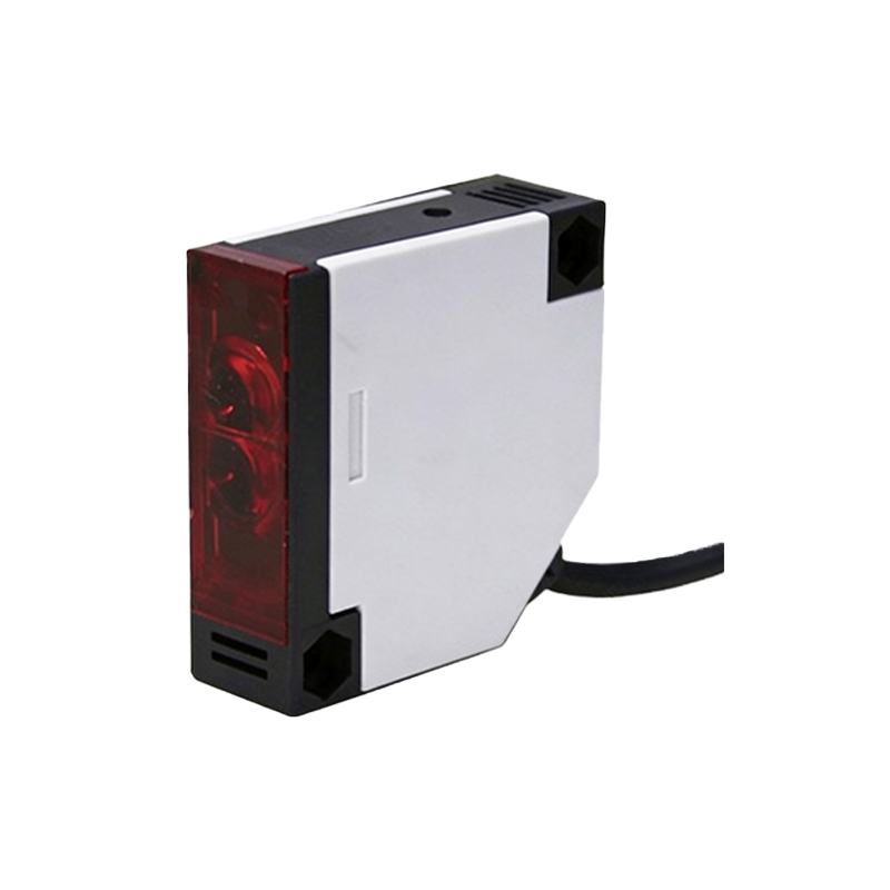
Wiring the Photoelectric Sensor
Start by connecting the sensor’s power wires: brown to +24V DC, blue to 0V (common). The black wire is the output signal. For a PNP sensor, connect the black wire to the PLC input terminal (e.g., I0.0). If using a relay, connect black to the relay coil positive terminal, and relay coil negative to 0V. Use a multimeter to verify voltage: between brown and blue should read 24V DC. When the sensor detects an object, the black wire voltage should switch to 24V (for PNP) or 0V (for NPN). Ensure proper shielding for long cable runs to prevent electrical noise.
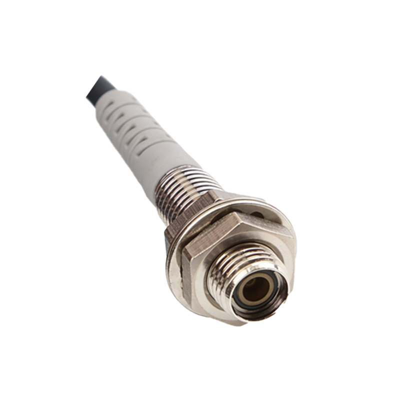
Integrating the Sensor with the Pneumatic Cylinder
The sensor’s output will trigger the cylinder’s solenoid valve. Wire the PLC output (e.g., Q0.0) to the solenoid valve’s positive terminal, and valve negative to 0V. In the PLC program, map the sensor input to control the valve. For example, when sensor input I0.0 is HIGH, set output Q0.0 HIGH to extend the cylinder. Use a timer to delay retraction if needed. Alternatively, use a standalone relay: sensor black wire to relay coil+, relay coil- to 0V; relay normally-open contact to valve+. This bypasses the PLC for simple on-off control.
Testing and Troubleshooting
After wiring, power up the system. Manually trigger the sensor (e.g., place an object in front) and observe the cylinder’s response. If the cylinder does not move, check: sensor power (24V across brown/blue), output signal voltage at black wire when triggered, and solenoid valve coil resistance (typically 50-200 ohms). Use a multimeter to verify continuity. Common issues include incorrect sensor output type (PNP vs. NPN mismatch), loose connections, or valve coil voltage drop. Adjust the sensor’s sensitivity potentiometer if the detection range is too short or too long. For noisy environments, add a flyback diode across the valve coil to suppress voltage spikes.
Safety and Best Practices
Always disconnect power before wiring modifications. Use fuses for overcurrent protection (e.g., 1A for sensor, 2A for valve). Label all wires for future maintenance. For high-speed applications, select a sensor with response time under 1 ms. Test the system without load first to verify logic. Document the wiring diagram and PLC code for reference. Consider using M12 connectors for modularity and quick replacement. Finally, ensure the sensor is mounted firmly and aligned correctly with the target to avoid false triggers.