Introduction to Photoelectric Sensors in Die Cutting
Photoelectric sensors play a critical role in modern die cutting machines, enabling precise detection of material presence, position, and alignment. As an electrical engineer specializing in industrial automation, I have observed that these sensors significantly reduce downtime and improve cut accuracy. By converting light signals into electrical outputs, they facilitate real-time feedback loops, ensuring consistent operation even at high speeds. For instance, through-beam sensors are ideal for detecting transparent films, while diffuse reflective sensors excel with opaque materials. Understanding the operational principles—such as emitter-receiver alignment and response time—is essential for system integration.
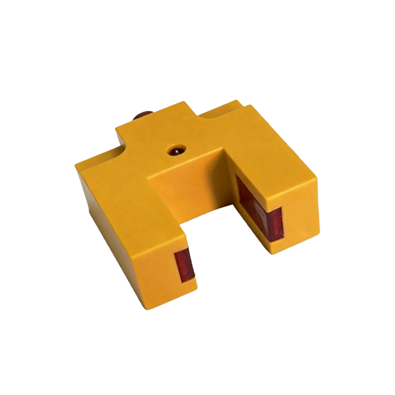
Key Sensor Types for Die Cutting Applications
Selecting the right sensor type depends on the material properties and machine design. Retro-reflective sensors are commonly used for non-transparent materials, as they offer reliable detection over medium distances. For challenging materials like glossy or dark films, background suppression sensors provide enhanced accuracy by ignoring reflections from the background. Fiber optic sensors, with their flexibility, are ideal for confined spaces within the die cutting press. In high-speed processes, sensors with fast switching frequencies (e.g., 1 kHz above) prevent missed detections. For example, in a label cutting line, using a contrast sensor ensures precise registration marks are identified, minimizing waste.
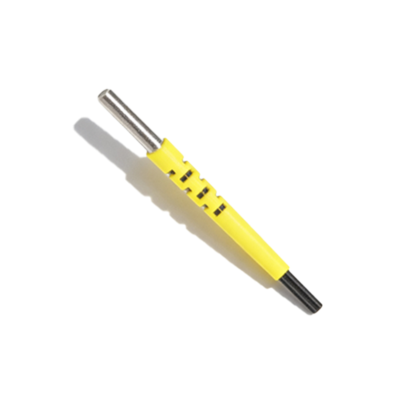
Installation Best Practices for Optimal Signal Stability
Proper installation is vital to avoid false triggers or signal loss. First, ensure the sensor’s sensing distance is calibrated based on the material’s reflective index. For through-beam pairs, mount the emitter and receiver with strict alignment, using brackets to absorb vibration. In dusty environments, equip sensors with air blow nozzles to keep lenses clean, as contamination can degrade performance. Additionally, shield sensor cables from high-frequency interference from servo drives by using twisted-pair wiring and ferrite cores. A common mistake is placing sensors near hydraulic systems, where oil mist can cause optical fogging. Always test the system under actual production conditions before full deployment.
Troubleshooting Common Photoelectric Sensor Issues
When sensors fail, the root cause often lies in environmental factors or electrical noise. If a sensor triggers intermittently, check for stray light from nearby welding arcs or reflective machine surfaces. Use a multimeter to verify the supply voltage stays within ±10% of the rated value, as voltage drops can cause erratic behavior. For misaligned sensors, a laser alignment tool can expedite corrections. In my experience, replacing old LED-based sensors with laser photoelectric sensors improves detection range and stability for small features like die registration marks. Documenting sensor performance data over time helps predict failures, enabling proactive maintenance.
Future Trends: Smart Sensors and Industry 4.0 Integration
The next generation of photoelectric sensors incorporates IO-Link communication, allowing real-time diagnostics and parameter adjustment from a central PLC. This connectivity enables predictive maintenance by monitoring sensor drift or contamination levels. For die cutting machines, integrating these smart sensors with edge computing can optimize cut speed based on material feedback, reducing waste. Engineers should also consider sensors with built-in temperature compensation for environments with thermal fluctuations. As we move toward fully automated factories, the ability to remotely calibrate sensors via HMI interfaces will become a standard requirement, enhancing overall equipment effectiveness (OEE).