Understanding the Core Difference: Transistor Output Type
In industrial automation, photoelectric sensors are widely used for object detection, and their output stages typically use either NPN (sinking) or PNP (sourcing) transistor configurations. The fundamental difference lies in how the output switches the load relative to the power supply. For an NPN output, the transistor connects the load to ground (0V) when activated, meaning the output switches to a low state. For a PNP output, the transistor connects the load to the positive supply voltage (+V), resulting in a high-state output when active. This distinction is critical for correct integration with PLCs, relays, or other controllers.
Identifying NPN Output: Sinking Signal Logic
An NPN photoelectric sensor acts as a current sink. When the sensor detects an object, the output terminal (often labeled as "Out" or "Load") becomes connected to the negative rail (0V). In a typical NPN configuration, the load (e.g., a PLC input module) is placed between the positive supply and the sensor output. When the sensor is triggered, current flows from +V through the load into the sensor output and then to ground. To test: connect the sensor to a power supply (e.g., 24VDC) and use a multimeter to measure voltage between the output and 0V. When the sensor is not triggered, the voltage should be near 0V (open collector); when triggered, it should be near 0V as well (sinking to ground). The key indicator is that the output pulls low.
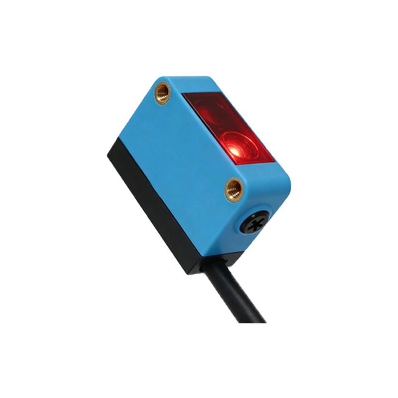
Identifying PNP Output: Sourcing Signal Logic
A PNP photoelectric sensor acts as a current source. When triggered, the output terminal connects to the positive supply voltage (+V). In a PNP setup, the load is connected between the sensor output and ground. Upon detection, current flows from +V through the sensor output into the load and then to ground. To verify: apply power and measure voltage between the output and 0V. When the sensor is not triggered, the voltage should be near 0V (open); when triggered, it should be near +24V (sourcing). This high-state output is typical for PNP sensors, which are common in European and some industrial PLC systems.
Practical Testing Methods with a Multimeter
The most reliable way to distinguish NPN from PNP is through simple voltage measurement. First, power the sensor with a stable DC supply (e.g., 24VDC from a transformer). Connect the brown wire to +V and the blue wire to 0V. Then, set your multimeter to DC voltage mode, place the black probe on the 0V terminal, and the red probe on the output wire (typically black or white). Observe the voltage change when an object is placed in front of the sensor: if the output goes from near 0V to near 0V (with slight drop), it is likely NPN; if it jumps from near 0V to near +V, it is PNP. Alternatively, use a test load (e.g., a 1kΩ resistor or an LED with series resistor) to see if the load activates when the output is asserted.
Common Wiring Pitfalls and Compatibility Issues
Mixing NPN and PNP sensors with incompatible PLC inputs is a frequent cause of field failures. Many PLC input modules are designed for sinking (PNP) or sourcing (NPN) signals. For example, a PLC with sourcing inputs expects a low signal from an NPN sensor, while a PLC with sinking inputs expects a high signal from a PNP sensor. Always check the PLC input type: if the PLC input module has a common terminal connected to +V (sourcing), use NPN sensors; if the common is connected to 0V (sinking), use PNP sensors. Also, note that some modern sensors offer both output types via a selector switch or configurable wiring, which simplifies integration.
Datasheet Interpretation and Manufacturer Markings
A reliable method for identification is to consult the sensor's datasheet or look for markings on the housing. Manufacturers often label the output type directly, e.g., "NPN NO" (normally open) or "PNP NC" (normally closed). The wiring diagram typically shows the transistor symbol: an NPN output is represented by an arrow pointing outward from the base (toward the load), while a PNP output has an arrow pointing inward. Additionally, the color code for standard M12 connectors follows IEC 60947-5-2: brown (+V), blue (0V), and black (output). However, some sensors use white for auxiliary functions, so always verify with the manual.