Introduction to Photoelectric Sensor Arrays
In modern industrial automation, precision and reliability are non-negotiable. A photoelectric sensor array, particularly a configuration of five units, offers enhanced detection capabilities for complex object recognition, positioning, and counting tasks. This article explores the design, implementation, and benefits of a 5-unit photoelectric sensor array, drawing on practical engineering experience to provide actionable insights for system integrators and plant engineers.
Core Components and Configuration
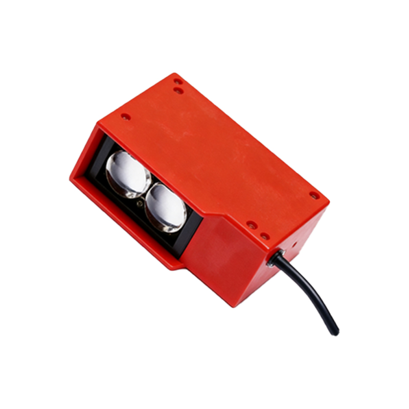
A typical 5-unit array consists of through-beam or reflective photoelectric sensors, each with an emitter and receiver. The sensors are mounted on a rigid frame with adjustable spacing to match target dimensions. Key specifications include sensing range (e.g., 0.1 to 10 meters), response time (below 1 ms), and output type (PNP/NPN). For optimal performance, align sensors perpendicular to the target path and shield them from ambient light interference using hoods or filters.
Wiring and Signal Integration
Each sensor in the array requires a dedicated power supply (typically 10-30 VDC) and a signal cable. Connect outputs to a programmable logic controller (PLC) or a dedicated counter module. Use twisted-pair shielded cables to reduce electrical noise in industrial environments. For a 5-unit array, configure the PLC to handle five discrete inputs, enabling logical operations such as AND/OR for presence detection or sequential timing for speed measurement.
Calibration and Sensitivity Adjustment
Calibration is critical for reliable detection. Begin by setting the sensitivity potentiometer on each sensor to its midpoint. Place a calibration target at the expected detection distance and adjust until the output LED indicates stable switching. For transparent or highly reflective objects, use polarizing filters to avoid false triggers. Document the final settings for each sensor unit to facilitate future maintenance.
Common Applications in Industry
The 5-unit array excels in high-speed counting on conveyor belts, detecting gaps in product flow, and verifying multi-component assembly. For example, in a bottling line, the array can simultaneously check cap presence, fill level, and label alignment. Another application is in robotics, where the array serves as a redundant safety zone around automated guided vehicles (AGVs), ensuring collision avoidance.
Troubleshooting and Maintenance Tips
Common issues include intermittent triggering due to vibration or dust accumulation. Regularly clean sensor lenses with a lint-free cloth and isopropyl alcohol. Verify alignment using a laser pointer tool. If one unit fails, replace it with a matched model to maintain consistent sensitivity. Log error codes from the PLC to identify recurring patterns, such as electrical noise from nearby motors.
Performance Optimization and Future Trends
To maximize throughput, adjust the array spacing to match the smallest object dimension, reducing detection gaps. Consider integrating the array with IoT gateways for real-time data logging and predictive maintenance alerts. Emerging trends include using time-of-flight (ToF) sensors in the array for 3D profiling, enabling more nuanced object classification. Retrofitting existing arrays with IO-Link communication can streamline configuration and diagnostics.
Conclusion
A 5-unit photoelectric sensor array, when properly configured and maintained, significantly enhances industrial automation reliability. By following the outlined wiring, calibration, and troubleshooting practices, engineers can achieve high-speed, accurate detection in demanding environments. Regular upgrades to sensor technology and communication protocols will future-proof the system against evolving production needs.