Introduction to Photoelectric Sensor Test Benches
In the realm of industrial automation and electrical engineering, photoelectric sensors are critical components for object detection, distance measurement, and process control. A dedicated test bench for these sensors is essential for ensuring reliability and performance under various operating conditions. This article outlines the key design considerations and testing procedures for a professional-grade photoelectric sensor test bench, focusing on accuracy, repeatability, and ease of integration into existing production lines.
Core Components and System Architecture
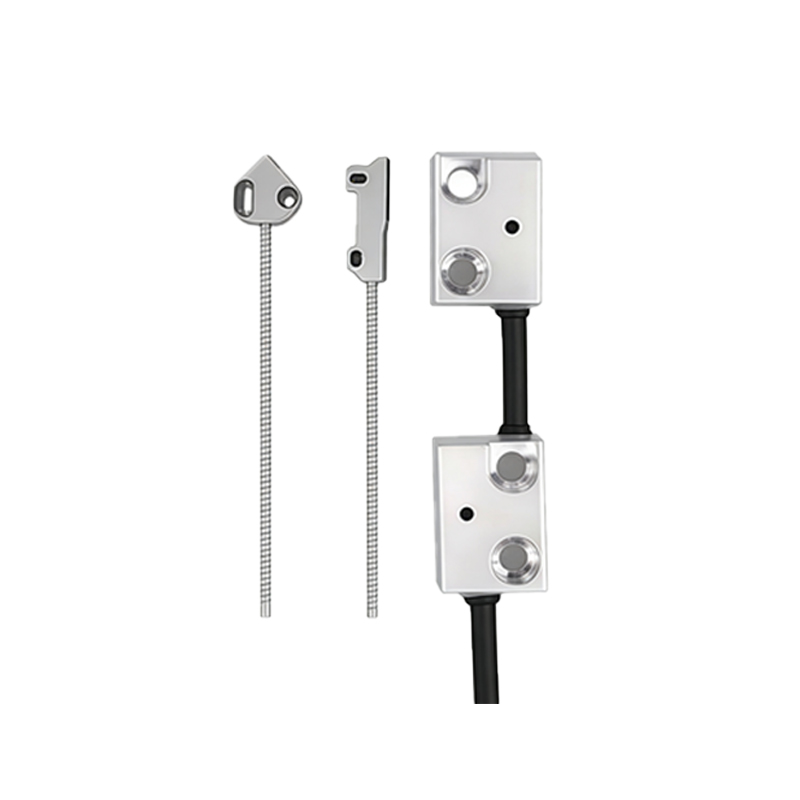
The test bench comprises three main subsystems: an adjustable target positioning mechanism, a multi-spectral light source array, and a data acquisition unit. The positioning mechanism uses a stepper motor-driven linear stage with a resolution of 0.01 mm to simulate different sensing distances. The light source array includes LED modules covering wavelengths from 400 nm to 950 nm, enabling testing of sensors with varying emitter types. For industrial-grade tests, we incorporate a programmable logic controller (PLC) and a National Instruments DAQ card for real-time signal monitoring.
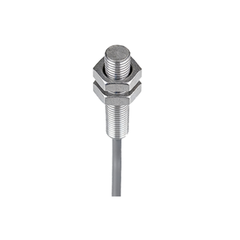
Test Procedures and Performance Metrics
Standard testing begins with a dark current measurement, followed by response time analysis under controlled ambient light conditions. Key metrics include switching frequency (up to 1 kHz for fast sensors), hysteresis, and sensing range deviation. The test bench automatically executes a pre-defined sequence: first, it records the sensor's output at 10 mm intervals from 0 to 500 mm; then, it evaluates the sensor's behavior under high-intensity ambient light (up to 10,000 lux). All data is logged to a secure database for long-term trending.
Calibration and Error Compensation
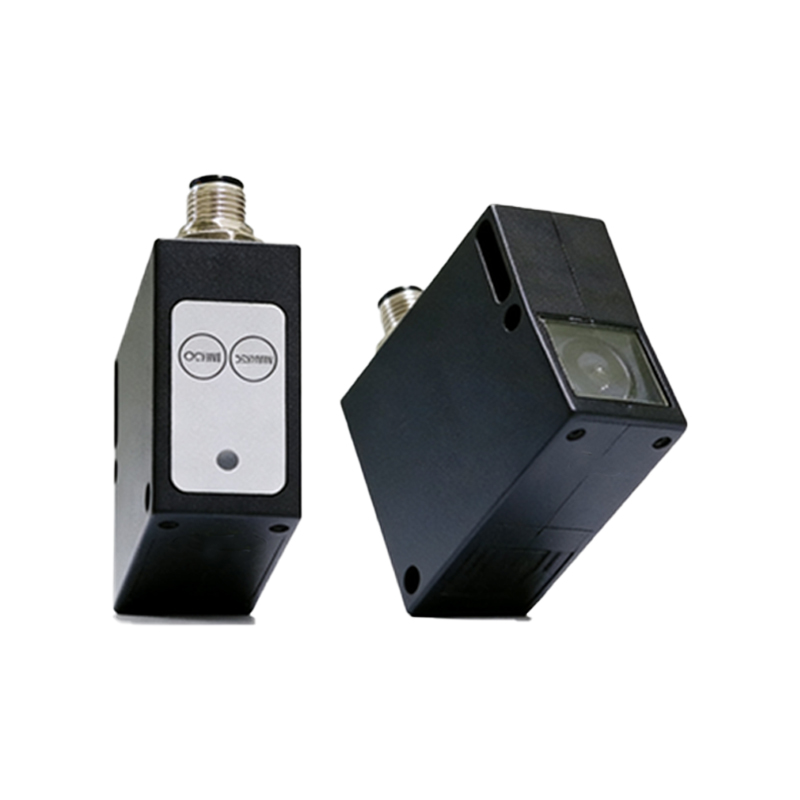
To ensure traceability, the test bench is calibrated quarterly against a NIST-traceable laser interferometer. We implement a compensation algorithm within the LabVIEW software to correct for thermal drift and mechanical backlash. The calibration coefficient is updated automatically based on environmental temperature readings from an integrated PT100 sensor. This approach reduces measurement uncertainty to less than 0.5% in industrial environments.
Integration with Production Line and Remote Monitoring
For factory deployment, the test bench supports Modbus TCP/IP and OPC UA protocols, allowing seamless integration with MES and SCADA systems. Engineers can remotely monitor test results via a secure web interface, which provides real-time dashboards and historical trend charts. The system also includes a self-diagnostic module that alerts maintenance staff if a test fixture or sensor becomes degraded, minimizing downtime.
Conclusion and Future Enhancements
This photoelectric sensor test bench design has proven effective in rigorous validation for automotive and packaging industries. Future upgrades will include automated handling via six-axis robot arm for high-throughput testing, and the addition of machine learning algorithms for predictive fault detection. By adhering to international standards such as IEC 60947-5-2, this test bench ensures consistent quality control for critical sensor applications.