Understanding Photoelectric Sensor Replacement
Photoelectric sensors are critical components in industrial automation, used for detecting objects, counting products, or ensuring safety in manufacturing lines. Replacing a faulty sensor requires precision and adherence to electrical safety standards. This guide outlines the technical process for swapping a photoelectric sensor, focusing on common types like through-beam, retro-reflective, and diffuse sensors. Always verify the sensor's specifications, such as voltage range (e.g., 10-30V DC) and output type (PNP or NPN), before proceeding.
Tools and Safety Precautions
Before starting, gather essential tools: a multimeter, screwdriver set (Phillips and flathead), wire strippers, electrical tape, and a replacement sensor matching the original model. Safety is paramount—disconnect the power supply to the control system and lockout/tagout (LOTO) the equipment to prevent accidental startup. Wear insulated gloves and safety glasses. Check the sensor's datasheet for wiring diagrams and mounting dimensions to avoid installation errors.
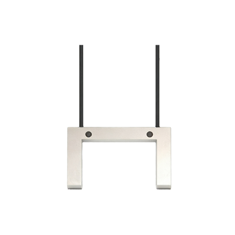
Step 1: Disconnect Power and Remove the Old Sensor
Turn off the main power source and verify zero voltage using a multimeter at the sensor terminals. Document the existing wiring connections by taking a photo or noting the wire colors (e.g., brown for V+, blue for V-, black for output). Loosen the mounting bracket screws and gently pull the sensor from its position. If the sensor is sealed with a gasket, inspect it for damage—replace if necessary. Carefully detach the wires from the terminal block or connector, labeling each wire for reconnection.
Step 2: Prepare the Replacement Sensor
Unpack the new sensor and confirm its model number matches the original. Adjust the sensing distance or sensitivity if adjustable (e.g., via a potentiometer) based on the application requirements. For example, a diffuse sensor might need a 500mm range for conveyor detection. Strip the wire ends (about 6-8mm) and tin them with solder if using screw terminals. For M12 connectors, ensure the pins align correctly (e.g., pin 1 for V+, pin 4 for output in some schemas).
Step 3: Install and Wire the New Sensor
Mount the new sensor in the same orientation as the old one, ensuring the lens is clean and unobstructed. Tighten the bracket screws to the manufacturer’s torque specification (e.g., 0.5 Nm for small sensors). Connect the wires according to your documented layout: brown to positive DC supply, blue to negative, black to the input module (for PNP sensors, output connects to the load; for NPN, output sinks to ground). Use a multimeter to check continuity and confirm no short circuits before powering up.
Step 4: Test and Calibrate the Sensor
Reconnect the power and observe the sensor’s indicator LED—typically green for power and yellow for output. Place a test object (e.g., a metal plate or opaque target) in the detection zone. For through-beam sensors, align the emitter and receiver; for retro-reflective, ensure the reflector is clean. Adjust the sensitivity pot until the output switches reliably. Use an oscilloscope if needed to verify response time (e.g.,<1ms for high-speed applications). Run a full cycle of the machine to confirm integration.
Step 5: Final Checks and Documentation
Inspect all connections for tightness and apply heat shrink or electrical tape to protect exposed wires. Record the replacement in the maintenance log, including the sensor’s serial number, installation date, and calibration settings. Monitor the sensor for 24 hours post-installation to detect any drift. If issues arise, re-verify the wiring diagram and consult the manufacturer’s FAQ. This process ensures minimal downtime and optimal performance in automated systems.