Introduction to Golf Photoelectric Sensors in Industrial Automation
Golf photoelectric sensors, named for their compact and durable design akin to a golf ball, are critical components in modern electrical engineering. These sensors use a light emitter and receiver to detect objects, changes in surface conditions, or distance variations without physical contact. In industrial automation, they offer high-speed response, reliability, and minimal maintenance, making them ideal for harsh environments. Their robust construction ensures consistent performance even with dust, vibration, or temperature fluctuations. Electrical engineers often integrate these sensors into conveyor systems, packaging lines, and robotic arms to achieve precise positioning and error detection.
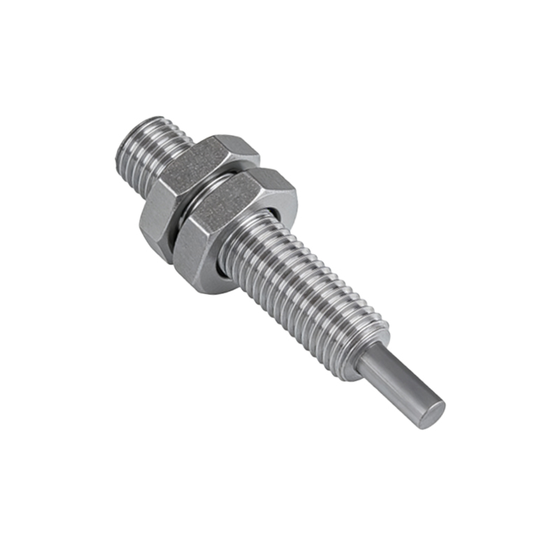
Key Technical Specifications and Operating Principles
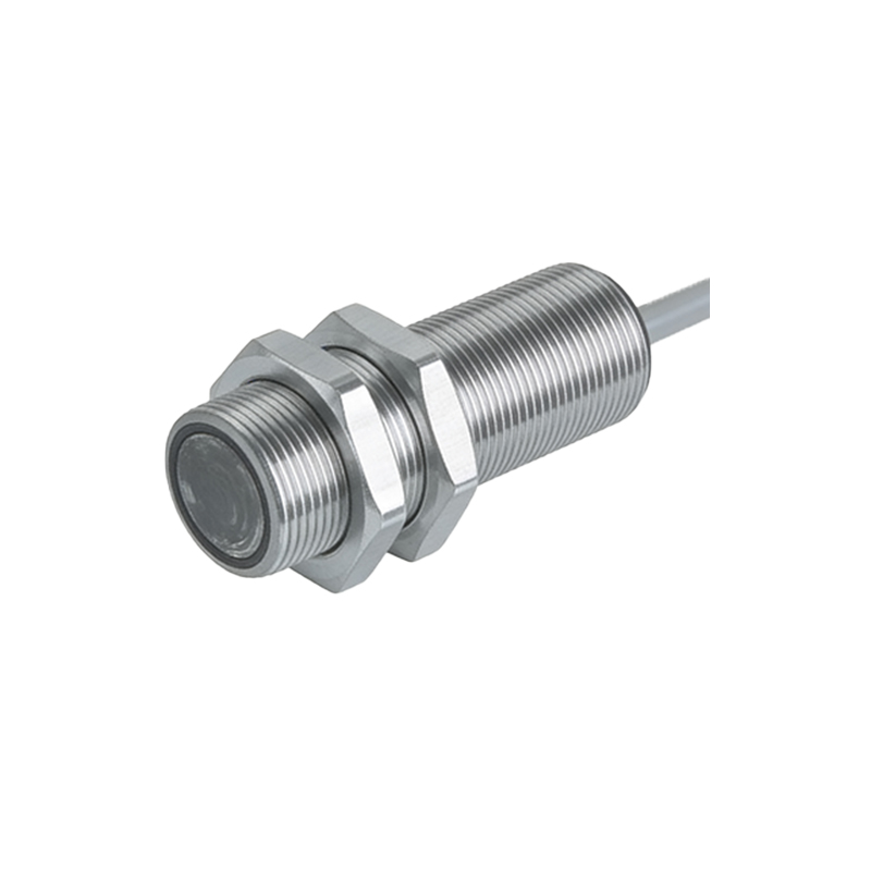
The core operation of a golf photoelectric sensor relies on modulated infrared or visible light. The emitter sends a beam, which is either reflected by a target or received directly. When the beam is interrupted or reflected, the sensor triggers an output signal. Key specifications include sensing range (from a few centimeters to several meters), response time (often under 1 millisecond), and output type (PNP, NPN, or analog). For electrical applications, engineers must consider supply voltage (typically 10-30VDC), ambient light immunity, and enclosure rating (e.g., IP67 for washdown environments). Understanding these parameters ensures accurate design for tasks like counting, presence detection, or edge alignment.
Installation and Alignment Best Practices
Proper installation is vital for maximizing sensor performance. Mount the sensor on a stable surface to avoid vibration-induced misalignment. For through-beam models, ensure the emitter and receiver are optically aligned within the beam angle (often 5-10 degrees). For retro-reflective types, use a suitable reflector and maintain a clean optical path. Electrical wiring should follow color-coded standards: brown for positive, blue for negative, and black for output. Use shielded cables in high-EMI areas to prevent false triggers. After installation, perform a test cycle to verify detection accuracy under actual operating conditions.
Troubleshooting Common Issues in Field Applications
Common issues include false signals from ambient light, dust accumulation on lenses, or electrical noise. To resolve false triggers, adjust the sensitivity potentiometer or use a narrow-beam lens. Clean lenses with a soft cloth and approved solvent; avoid abrasive materials that scratch the optics. For noise issues, check grounding and add ferrite cores to signal wires. If the sensor fails to detect certain materials (e.g., transparent glass or dark objects), switch to a polarized or background-suppression model. Always consult the manufacturer's datasheet for specific threshold settings.
Future Trends and Integration with IoT Systems
The latest golf photoelectric sensors now feature IO-Link communication, enabling real-time diagnostics and parameter changes via a central controller. This integration supports Industry 4.0 initiatives by providing data on sensor health, count accuracy, and environmental conditions. Engineers can use this data for predictive maintenance, reducing downtime. Additionally, miniaturization and lower power consumption allow these sensors to be deployed in battery-operated remote devices. As electrical systems become more connected, the role of golf photoelectric sensors will expand into smart grids, logistics, and autonomous vehicles.