1. Overall Housing and Enclosure Design
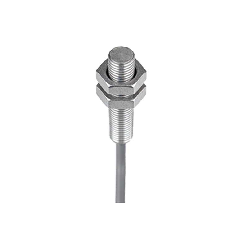
The infrared photoelectric sensor is encased in a robust housing typically made from industrial-grade ABS plastic or metal alloys such as aluminum or stainless steel. This enclosure provides ingress protection ratings of IP67 or higher, ensuring resistance to dust, water, and mechanical shock. The housing often features a cylindrical or rectangular shape, with threaded sections for easy mounting in industrial automation setups. A transparent lens or window, often made of polycarbonate or glass, is integrated into the front face to allow infrared light transmission while maintaining seal integrity.
2. Optical System: Emitter and Receiver Modules
At the core of the sensor lies the optical system, comprising an infrared LED as the emitter and a photodiode or phototransistor as the receiver. The emitter typically operates at a wavelength of 850 nm or 940 nm, optimized for minimal ambient light interference. These components are mounted on a compact PCB, aligned precisely with the lens. Some designs incorporate a collimating lens to focus the emitted beam, enhancing detection range and accuracy. The receiver module is often paired with an optical filter to block visible light, ensuring reliable detection in bright environments.
3. Signal Processing Circuitry
Behind the optical components, the signal processing circuit is built around a microcontroller or dedicated amplifier IC. This circuit amplifies the weak photocurrent from the receiver, filters out noise using analog or digital filters, and converts the signal into a binary output (e.g., NPN, PNP, or push-pull). Advanced models include automatic gain control to adapt to varying background conditions. The circuitry also includes a built-in indicator LED, often red or green, to visually confirm detection status.
4. Output and Connection Interface
The output stage typically features a three-wire configuration: power (VCC), ground (GND), and signal output. Connectors may be pre-wired cables, M8, or M12 circular connectors, common in industrial control systems. The output can be configured as normally open or normally closed, with response times as low as 1 millisecond. Some sensors include additional functions like a time-delay feature or a test input for system diagnostics.
5. Adjustment and Calibration Components
Many infrared photoelectric sensors include a potentiometer or multi-turn trimmer for sensitivity adjustment. This component is usually located inside the housing or accessed via a sealed screw on the sensor body. For through-beam or retro-reflective models, alignment aids such as a visible red laser pointer or a two-color LED indicator are integrated to assist installation. Additionally, some designs feature a teach-in button for digital configuration, storing threshold values in non-volatile memory.
6. Environmental Protection and Mechanical Durability
To withstand harsh factory conditions, the sensor includes an internal O-ring seal between the housing and lens, preventing moisture ingress. The PCB is often coated with a conformal layer for humidity and chemical resistance. Thermal management is achieved via a metal heat sink or thermal pad beneath the power components. Vibration resistance is enhanced by potting the internal electronics with epoxy resin, ensuring long-term reliability in high-vibration machinery.