Introduction to Photoelectric Sensors in Printers
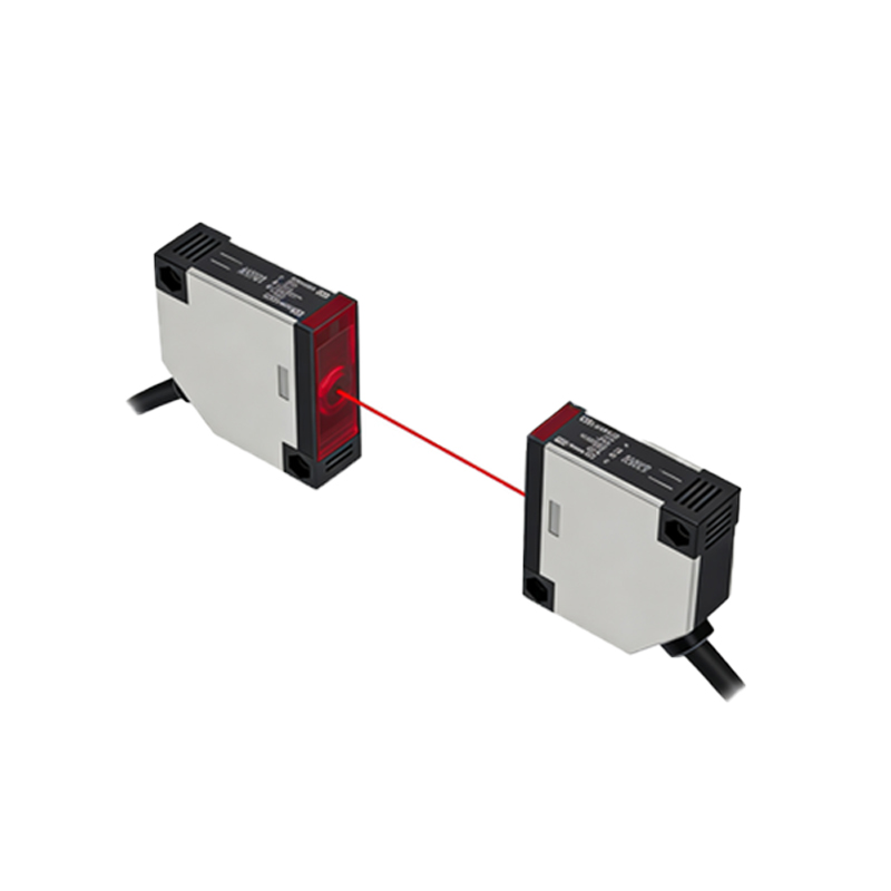
Photoelectric sensors are critical components in modern printers, enabling precise paper detection, alignment, and ink delivery. As an electrical engineer, understanding their measurement parameters is essential for troubleshooting and design optimization. These sensors typically operate in the infrared or visible spectrum, using light-emitting diodes (LEDs) and phototransistors to detect changes in reflectivity or transmittance.
Key Measurement Parameters
When evaluating printer photoelectric sensors, focus on three primary metrics: response time, sensitivity, and signal-to-noise ratio (SNR). Response time, usually in microseconds, determines how quickly the sensor reacts to paper movement. Sensitivity refers to the minimum detectable change in light intensity, often measured in lux or milliwatts. SNR must exceed 10:1 for reliable operation in dusty environments.
Testing Methods for Sensor Performance
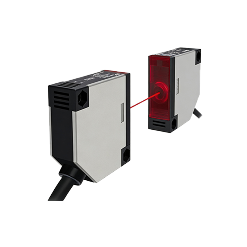
Use an oscilloscope and a controlled light source to measure sensor output waveforms. Connect the sensor to a 5V DC supply and monitor the collector voltage of the phototransistor. Simulate paper passage with a reflective target moving at typical printer speeds (e.g., 10 inches per second). Record the voltage drop and rise times—ideal values are below 100 microseconds for high-speed printers.
Calibration and Environmental Considerations
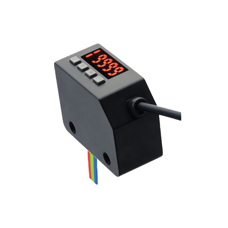
Calibrate sensors using a reference target with known reflectivity (e.g., 80% white paper). Adjust the LED drive current to achieve a mid-range output voltage (2.5V for a 0-5V range). Account for ambient light interference by shielding the sensor or using modulated light signals. Temperature variations can shift sensitivity by up to 5% per degree Celsius, so specify sensors with thermal compensation.
Common Failures and Diagnostic Tips
Frequent issues include LED degradation (reduced output over 10,000 hours), phototransistor saturation from excessive dust, and mechanical misalignment. Use a multimeter to check forward voltage of the LED (typically 1.2-1.8V) and dark current of the phototransistor (under 1 microamp). If the sensor fails to trigger, inspect the lens for contamination and verify the supply voltage ripple is below 50mV peak-to-peak.
Conclusion: Optimizing Sensor Integration
Reliable measurement of photoelectric sensors ensures consistent printer performance. Engineers should document baseline readings during assembly and schedule periodic re-calibration based on usage hours. For advanced applications, consider using differential sensors to cancel common-mode noise. By adhering to these measurement practices, you can extend sensor lifespan and reduce field failures.