Understanding the Feedback Line in Photoelectric Sensors
In industrial automation, photoelectric sensors are essential for detecting objects, distances, and positions. A critical component often overlooked is the feedback line, which transmits the sensor's output signal back to the controller or PLC. This line ensures real-time communication, allowing the system to adjust operations based on the sensor's readings. For example, in a conveyor belt system, the feedback line carries the signal when an object breaks the light beam, triggering a stop or divert action. Without a reliable feedback line, the sensor’s data becomes useless, leading to production errors or safety hazards. Engineers must consider cable shielding, connector quality, and signal integrity to minimize noise and latency.
Key Design Considerations for Feedback Lines
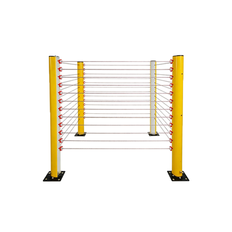
When designing or selecting feedback lines for photoelectric sensors, several factors influence performance. First, cable length: longer runs can cause signal attenuation, requiring shielded twisted-pair cables to maintain strength. Second, environmental resistance: in harsh industrial settings, feedback lines must withstand temperature extremes, moisture, and electromagnetic interference (EMI). Using materials like PVC or PUR jackets with metal braid shielding is common. Third, connector compatibility: ensure the feedback line’s connector matches the sensor’s output type (e.g., NPN, PNP, or analog). A mismatch can lead to open circuits or false signals. For instance, in a food processing plant, using a feedback line with IP69K rating prevents washdown damage.
Common Issues and Troubleshooting Tips
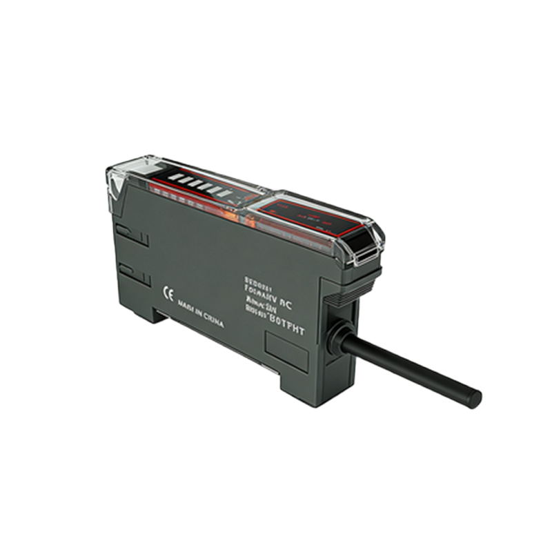
Feedback line failures often manifest as intermittent signals, false triggers, or no response. Common causes include cable breaks due to flexing, corrosion at connectors, or EMI from nearby machinery. To diagnose, start with a visual inspection: check for cuts, kinks, or loose connections. Use a multimeter to test continuity and voltage levels. For intermittent issues, try replacing the cable with a higher-flex rated version, such as continuous-flex cables for robotics. In one case, a factory fixed a recurring sensor error by rerouting the feedback line away from a high-voltage motor, eliminating EMI. Regular maintenance, like cleaning connectors and securing cables, reduces downtime.
Future Trends in Feedback Line Technology
Advancements in industrial IoT (IIoT) are driving smarter feedback lines. Modern sensors now integrate with digital protocols like IO-Link, where the feedback line carries not just on/off signals but also diagnostic data. This allows predictive maintenance—e.g., detecting signal degradation before a failure occurs. Additionally, wireless feedback lines are emerging for mobile robots, using industrial Wi-Fi or Bluetooth LE. However, wired solutions remain dominant for high-speed or safety-critical applications due to lower latency. Engineers should plan for these trends by selecting sensors with backward-compatible feedback interfaces, ensuring future upgrades without rewiring.