Understanding Photoelectric Sensors in Conveyor Systems
Photoelectric sensors are critical components in modern conveyor lines, providing non-contact detection of objects, packages, or materials. These sensors use light beams to sense presence, position, or absence of items, ensuring smooth automation and safety. For an electrical engineer, proper wiring is essential to avoid false triggers, signal noise, or equipment damage. This guide focuses on the typical wiring diagram for a through-beam or retro-reflective sensor used in industrial conveyors.
Common Sensor Types and Their Wiring Requirements
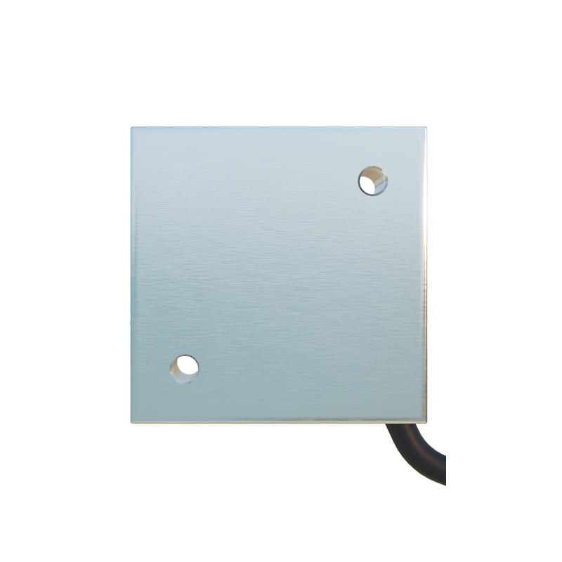
There are three main types: through-beam (emitter and receiver), retro-reflective (sensor and reflector), and diffuse (sensor only). Each has a distinct wiring layout. Most sensors have three or four wires: brown (positive power supply, typically 10-30 VDC), blue (negative/ground), black (NPN output, sinking current), or white (PNP output, sourcing current). For conveyor applications, PNP sensors are often preferred in PLC systems because they provide a positive signal. Ensure your power supply matches the sensor’s voltage rating, usually 24 VDC.
Step-by-Step Wiring Diagram for a Standard Conveyor Sensor
Begin by identifying the sensor’s cable colors. Connect the brown wire to the +24 VDC terminal of the power supply. Connect the blue wire to the 0 VDC (ground). For a PNP sensor, the black wire serves as the output, which connects to the PLC input module (e.g., digital input pin). If using an NPN sensor, the black wire connects to the PLC’s common ground, and the load is connected between the output and positive supply. Always use a 1A fuse in series with the power line to protect against shorts. For long cable runs (over 50 meters), use shielded cable and ground the shield at the power supply end to reduce electromagnetic interference.
Wiring a Retro-Reflective Sensor with a Reflector
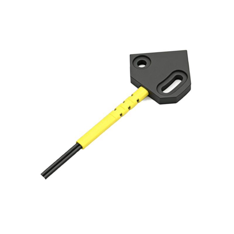
Retro-reflective sensors require a reflector mounted opposite the sensor. Wire the sensor the same way as a through-beam unit: brown to +24V, blue to ground, and black to PLC input. However, note that the sensor’s alignment is critical; the reflector must be clean and perpendicular to the light beam. In dusty conveyor environments, use a polarized retro-reflective sensor to avoid false detection from shiny surfaces. The wiring diagram remains identical, but the sensor’s sensitivity adjustment potentiometer (if present) should be set to ignore ambient light.
Common Wiring Mistakes and Troubleshooting
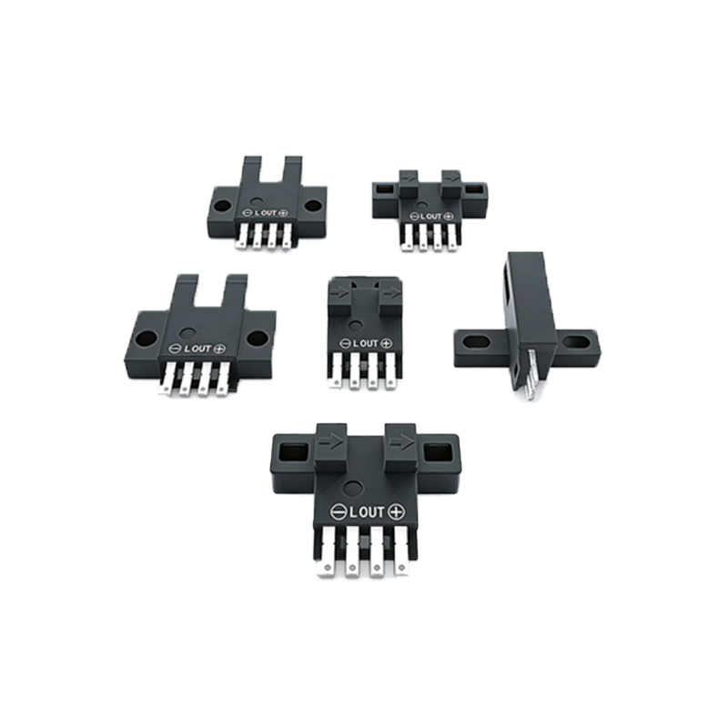
A frequent error is reversing the NPN and PNP wiring, leading to no signal or constant on state. Verify your PLC input type before wiring. Another issue is using too thin a wire gauge for long distances, causing voltage drop; use at least 0.5 mm² (AWG 20) cable for runs up to 100 meters. If the sensor triggers intermittently, check for loose connections, corroded terminals, or nearby high-power cables. Use a multimeter to measure voltage at the sensor terminals: it should be within 10-30 VDC. Also, ensure the sensor’s sensing distance matches your conveyor speed; fast-moving items may require a sensor with a faster response time (e.g.,<1 ms).
Safety and Best Practices for Installation
Always disconnect power before wiring to prevent electric shock. Use cable glands or strain relief to protect connections from mechanical stress. Label cables clearly for future maintenance. In explosive or wet environments, select sensors with IP67 or higher ratings. For high-vibration conveyor lines, secure cables with zip ties and avoid sharp bends. Finally, test the sensor by passing a standard product through the beam; adjust the sensitivity or alignment as needed. Document the wiring diagram in the maintenance manual for quick troubleshooting.