Introduction to Cylinder Photoelectric Sensors
Cylinder photoelectric sensors are critical components in industrial automation, used to detect the position of piston rods in pneumatic or hydraulic cylinders. These sensors replace traditional mechanical limit switches, offering faster response times and longer service life. Proper wiring is essential to ensure reliable operation and prevent signal interference in harsh factory environments.
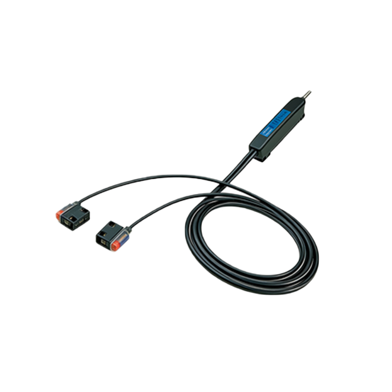
Understanding Sensor Types and Output Configurations
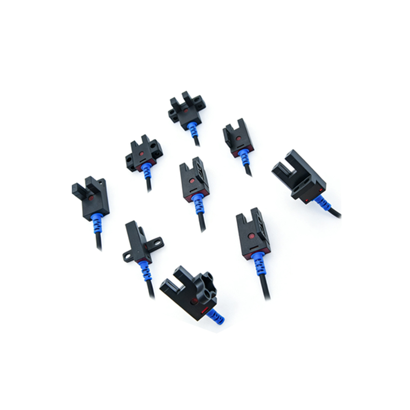
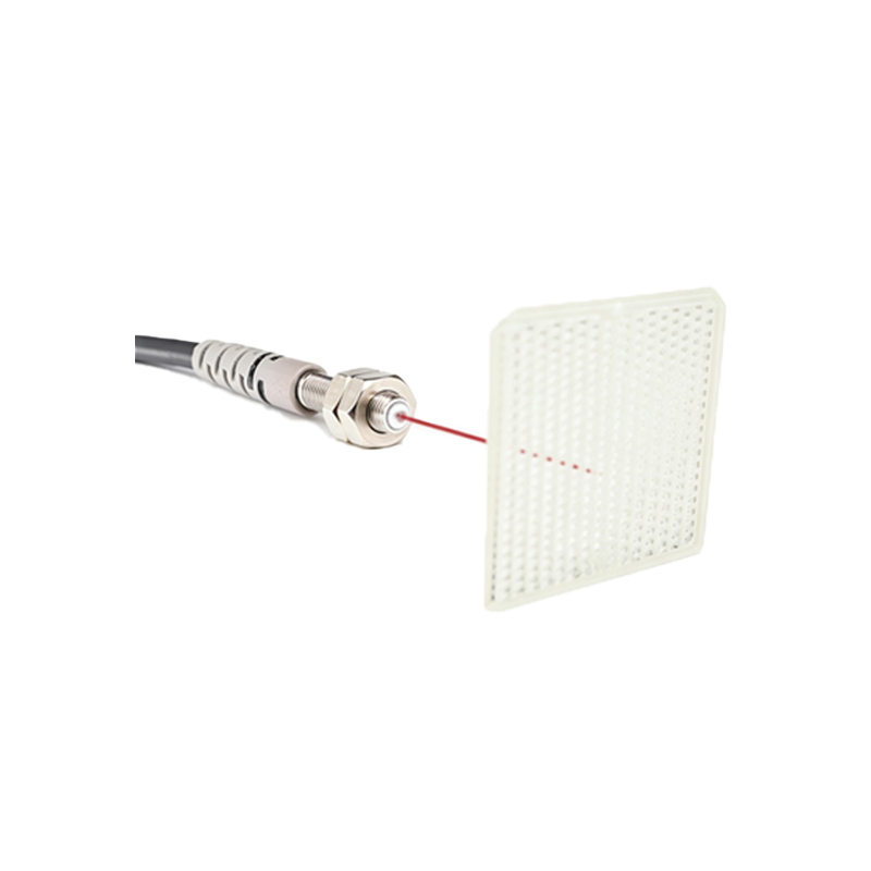
Before wiring, identify the sensor type: diffuse, through-beam, or retro-reflective. Most cylinder sensors feature either NPN (sinking) or PNP (sourcing) output. For PLC inputs, NPN is common in Asia, while PNP dominates in Europe and the US. Check the sensor datasheet for voltage range (typically 10-30V DC) and current rating (usually 100-200mA). If using a 3-wire sensor, the three wires are: brown (V+), blue (GND), and black (output signal).
Step-by-Step Wiring Procedure for a 3-Wire Cylinder Sensor
1. Power off all equipment before starting. Strip 5-7mm of insulation from each wire end.
2. Connect the brown wire to the positive terminal of a 24V DC power supply.
3. Connect the blue wire to the common ground (0V) of the power supply.
4. Connect the black output wire to the PLC input module. For NPN output, the signal is low when active; for PNP, it is high.
5. Use a multimeter to verify voltage between brown and blue (should read 24V). Then trigger the sensor by moving the cylinder piston; the black wire should toggle between 0V and 24V.
6. Secure all connections with screw terminals or M12 connectors, and apply dielectric grease for moisture protection.
Wiring for 2-Wire and 4-Wire Sensors
2-wire sensors are simpler: connect one wire to power and the other to the PLC input. However, they have higher leakage current and are less common in new installations. 4-wire sensors offer separate NO (normally open) and NC (normally closed) outputs. Wire the brown/blue for power, then connect the NO black wire and NC white wire to separate PLC inputs. Use a pull-up or pull-down resistor if the PLC input lacks internal impedance.
Troubleshooting Common Wiring Issues
If the sensor fails to trigger, check polarity: reversed brown and blue can damage the sensor. For intermittent signals, inspect for loose connections or cable damage from cylinder movement. Use shielded cables for long runs (over 10 meters) to reduce electromagnetic interference. Measure the load current with a clamp meter; an overloaded sensor may drop voltage. Finally, verify the sensor’s sensing distance and alignment with the cylinder target.
Best Practices for Industrial Environments
Always use strain reliefs near the sensor head to prevent cable pull-out. Label all wires according to the wiring diagram. For high-vibration applications, apply thread-locking compound on connector screws. Implement a routine inspection schedule to check for corrosion or abrasion. Consider using pre-wired M8 or M12 connectors for field-replaceable sensors, which simplify maintenance and reduce downtime.