2026-06-01
Tech Hub
By 创始人
How to Short Circuit a U-Shaped Photoelectric Sensor: A Professional Guide
Understanding the U-Shaped Photoelectric Sensor
A U-shaped photoelectric sensor, also known as a fork sensor, consists of a transmitter and receiver housed in a single U-shaped body. The light beam travels across the gap between the two arms. When an object interrupts this beam, the sensor’s output state changes. Shorting such a sensor refers to forcing its output to a fixed state, typically for testing, bypassing, or troubleshooting purposes. This process must be done with caution to avoid damaging the sensor or connected equipment.
Safety Precautions Before Shorting
Before attempting any shorting procedure, disconnect the sensor from the power supply to prevent electrical shock or short-circuit damage. Verify the sensor’s wiring diagram: common configurations include three-wire (brown for V+, blue for V-, black for output) or four-wire types (with additional alarm or test lines). Use a multimeter to confirm the output type—NPN (normally open or closed) or PNP—as this affects the shorting method. Never short the output directly to power or ground without proper resistance or control, as this can destroy the output transistor.
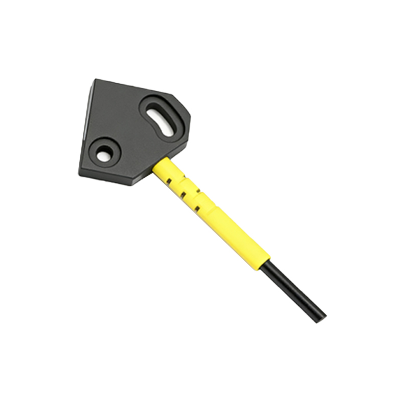
Identifying Output Type and Wiring
For NPN sensors, the output (black wire) sinks current to ground when activated. To short it to a constant “on” state, connect the black wire to the blue wire (0V) through a 1kΩ resistor. For PNP sensors, the output sources current to V+. Short it to a constant “on” state by connecting the black wire to the brown wire (V+) via a 1kΩ resistor. Always use a current-limiting resistor to prevent excessive current flow. If the sensor has a test input (white wire), you may also apply a voltage signal to simulate interruption, but this is not a true short.
Step-by-Step Shorting Procedure for NPN Sensors
1. Power off the sensor and disconnect it from the load. 2. Strip a small section of the black (output) and blue (ground) wires. 3. Solder or use a terminal block to connect a 1kΩ, 0.25W resistor between the black and blue wires. 4. Insulate the connection with heat shrink tubing or electrical tape. 5. Reconnect the sensor to the power supply. The output will now remain low (active) continuously. 6. Verify with a multimeter: the voltage between black and blue should be near 0V. To restore normal operation, remove the resistor.
Step-by-Step Shorting Procedure for PNP Sensors
1. Power off and disconnect the sensor. 2. Connect a 1kΩ resistor between the black (output) and brown (V+) wires. 3. Insulate the joint securely. 4. Power on the sensor. The output will now remain high (active) continuously. 5. Measure voltage between black and blue: it should read near the supply voltage (e.g., 24V). 6. Remove the resistor to return to normal mode.
Alternative Method Using a Test Input
Some U-shaped sensors feature a test pin (often white or gray wire) that allows external control of the output. Applying a voltage (typically V+) to this pin forces the output to switch. This method is safer and non-destructive but requires a controlled signal source. Refer to the sensor datasheet for exact test pin specifications. Do not use this as a permanent short, as it may interfere with sensor logic.
Verification and Troubleshooting
After shorting, test the sensor with an object to ensure the output remains fixed. If the output fluctuates, check the resistor connection and polarity. If the sensor becomes hot or emits smoke, immediately disconnect power and inspect for incorrect wiring. For long-term bypassing, consider using a dedicated relay or logic controller instead of a direct short to avoid overheating the sensor’s internal components. Always document modifications for future maintenance.