Introduction to Transparent Object Photoelectric Sensors
Transparent object photoelectric sensors are essential components in industrial automation, designed to detect clear, translucent, or glass-like materials that often challenge standard sensors. Unlike conventional photoelectric sensors that rely on reflection or beam interruption, these specialized devices leverage advanced optical principles, such as polarized light or retroreflective methods, to accurately sense transparent targets. Engineers in packaging, bottling, and glass manufacturing frequently deploy these sensors to ensure reliable detection without false triggers caused by background reflections or material clarity.
Core Operating Principle
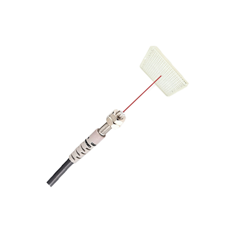
The fundamental schematic of a transparent object photoelectric sensor consists of a light emitter, typically an LED or laser diode, and a photodetector, such as a phototransistor or photodiode. The emitter projects a focused beam of light, often in the infrared spectrum, toward a retroreflector or directly at the target. When a transparent object passes through the beam path, it alters the light’s intensity or polarization state. The receiver circuit detects these changes and converts them into a digital output signal. Key to this design is the use of a modulated light source to filter out ambient light interference, thereby enhancing detection reliability.
Key Circuit Blocks in the Schematic
The schematic diagram typically includes four main circuit blocks: the emitter driver circuit, the receiver amplifier, the signal processing unit, and the output stage. The emitter driver stabilizes the LED current to maintain consistent light output, often using a constant current source. The receiver amplifier, usually a transimpedance amplifier, converts the photodetector’s current into a voltage signal. This signal then passes through a bandpass filter tuned to the modulation frequency, which isolates the sensor’s signal from ambient noise. The processed signal is compared against a threshold in a comparator, and the output stage drives a transistor or relay for industrial connectivity.
Retroreflective Design for Transparent Targets
For transparent objects, a retroreflective configuration is preferred. In this setup, the emitter and receiver are housed in the same unit, with a separate reflector placed opposite. The beam travels to the reflector and returns to the receiver. A transparent target passing between the unit and the reflector causes a slight beam deflection or intensity reduction due to refraction or reflection from the object’s surface. The schematic includes a polarizing filter on the emitter and receiver to eliminate false signals from shiny backgrounds. This design ensures detection even for high-clarity materials like glass or acrylic.
Practical Implementation Considerations
When designing or analyzing the schematic, engineers must account for several real-world factors. The emitter wavelength should be matched to the photodetector’s peak sensitivity, commonly 940nm for infrared systems. The receiver’s bandwidth must support the modulation frequency, typically 1-5kHz, to avoid response delays. Additionally, hysteresis in the comparator circuit prevents output chatter near the detection threshold. Power supply decoupling capacitors near the ICs are critical to suppress noise from industrial machinery. Engineers should also include a sensitivity adjustment potentiometer to calibrate the sensor for different material types and mounting distances.
Testing and Troubleshooting the Schematic
Testing the sensor circuit involves verifying the emitter output with an oscilloscope, checking the receiver’s signal waveform under both clear and blocked conditions. If the output remains high or low regardless of target presence, inspect the comparator threshold voltage or the photodetector’s biasing. Common issues include misaligned optical paths, degraded emitters, or contamination on the lens. For transparent object detection, ensure the polarizing elements are correctly oriented; otherwise, the sensor may fail to distinguish between the target and the background. Using a test jig with known transparent samples can validate the circuit’s performance.
Applications and Future Trends
These sensors are widely used in beverage filling lines, pharmaceutical packaging, and automotive glass handling. The schematic principles discussed are also evolving with the integration of digital processing, such as embedded microcontrollers that adjust thresholds dynamically. Future designs may incorporate time-of-flight or multi-wavelength analysis for enhanced material differentiation. Understanding the basic schematic empowers engineers to customize or troubleshoot these sensors for specific industrial challenges.