Introduction to Photoelectric Sensor Wiring
In the field of industrial automation, photoelectric sensors are essential components for detecting objects, distances, and material presence. These sensors typically come with color-coded wires to simplify installation and troubleshooting. Understanding these color codes is crucial for electrical engineers and technicians to ensure correct wiring, prevent system failures, and maintain operational efficiency. This article focuses on the most common wire color standards used in photoelectric sensors, particularly in the context of DC-powered devices.
The Standard Color Code for DC Power Wires
For most photoelectric sensors operating on direct current (DC), the power supply wires follow a widely accepted color scheme. The brown wire generally represents the positive terminal, typically connected to a 10-30 VDC power source. The blue wire serves as the negative or ground terminal. This pairing is consistent across many industrial sensors, including proximity sensors and photoelectric units. It is critical to verify the voltage rating before connection, as mismatched polarity can damage the sensor.
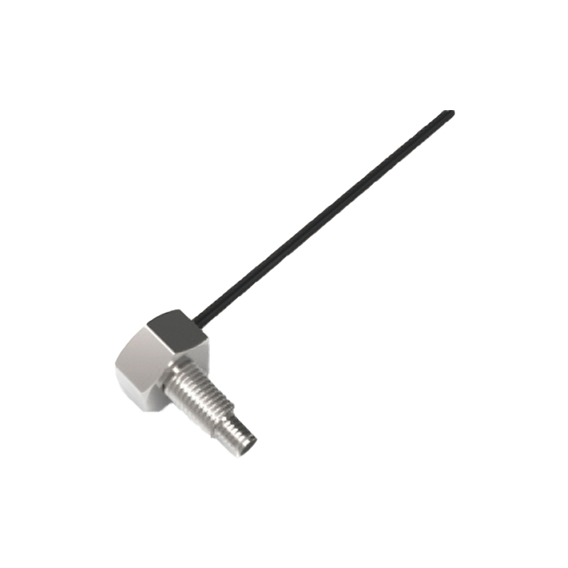
Output Wire Color Codes: NPN vs. PNP Configurations
The output wire color indicates the sensor's switching logic. In NPN (sinking) configurations, the black wire is the output signal wire, which goes low when the sensor is active. In PNP (sourcing) configurations, the black wire goes high when the sensor is triggered. However, some manufacturers use white or gray wires for auxiliary outputs or alarm signals. For example, a white wire might be used for a diagnostic output, while a gray wire could indicate a complementary output. Always consult the sensor datasheet to confirm the logic type.
Three-Wire and Four-Wire Sensor Variations
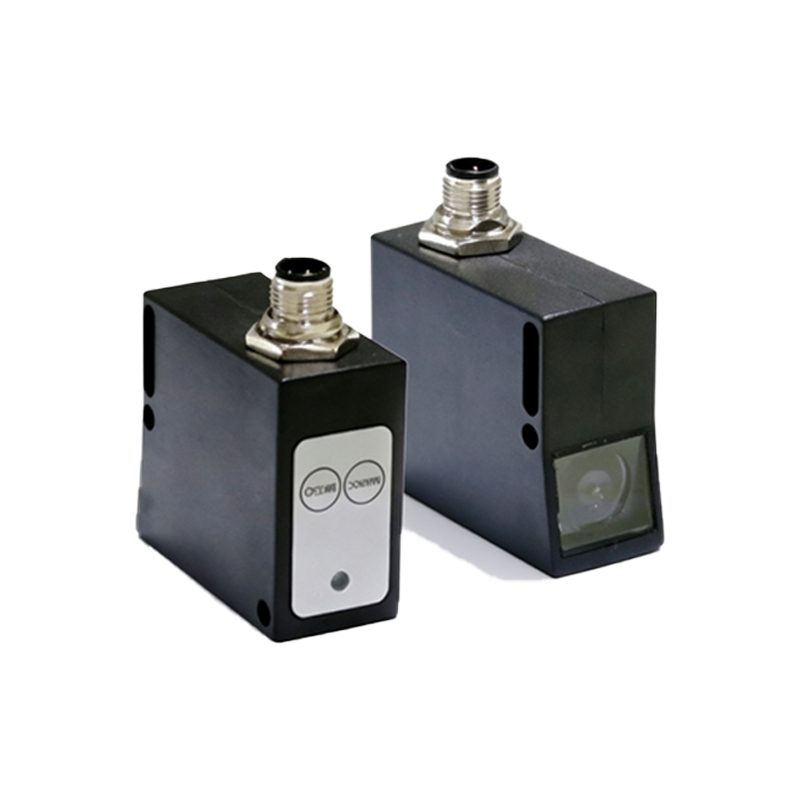
Three-wire photoelectric sensors are common, with brown (power), blue (ground), and black (output) wires. Four-wire sensors add an additional output, often with a white wire for a second switching channel, such as a normally open and normally closed pair. In some models, the fourth wire is used for a synchronization or reset function. The color coding for these additional wires may follow the IEC 60947-5-2 standard, but industrial vendors like Banner, SICK, and Omron may have proprietary schemes. Always cross-reference with the provided wiring diagram.
Special Cases: AC Sensors and Specialty Wires
For alternating current (AC) photoelectric sensors, the color code differs. Common AC units use red and blue wires for line and neutral, with a green or green-yellow wire for ground. Additionally, some sensors include a shield wire, often bare or with a drain conductor, which must be connected to earth ground to reduce electromagnetic interference. Fiber optic sensors may also have a thin fiber cable instead of wires, but the electrical interface still follows the same color rules. For high-accuracy applications, verify if the sensor uses a separate power and output wire set.
Best Practices for Wiring and Troubleshooting
When installing photoelectric sensors, always power down the system before connecting wires. Use a multimeter to confirm voltage levels and test continuity. If the sensor does not operate as expected, check the wire color against the datasheet. Common errors include swapping brown and blue wires or connecting the output wire to the wrong input on the PLC. Label wires if the color codes fade or are non-standard. For retrofits, match the color scheme of the existing system to avoid confusion. Remember that environmental factors like moisture or vibration can affect wire integrity, so use proper strain relief and sealing.