Understanding the Slot-Type Photoelectric Sensor
Slot-type photoelectric sensors, also known as fork sensors, are critical components in automated manufacturing lines, packaging systems, and conveyor controls. They consist of a U-shaped housing with an emitter on one side and a receiver on the other, detecting objects that pass through the gap. When a sensor fails—due to dust buildup, electrical surges, or mechanical wear—it can halt production. This guide provides a systematic approach to replacement, ensuring minimal downtime and optimal performance.
Safety Precautions Before Starting
Before any work, ensure the system is completely powered down. Lock out and tag out the main power source to prevent accidental startup. Wear insulated gloves and safety glasses, especially if working in a dusty or oily environment. Verify that the replacement sensor matches the original specifications: check voltage (typically 10-30V DC for standard models), output type (NPN or PNP), and sensing distance (usually 5-30 mm). Use a multimeter to confirm zero voltage at the sensor terminals before touching any wires.
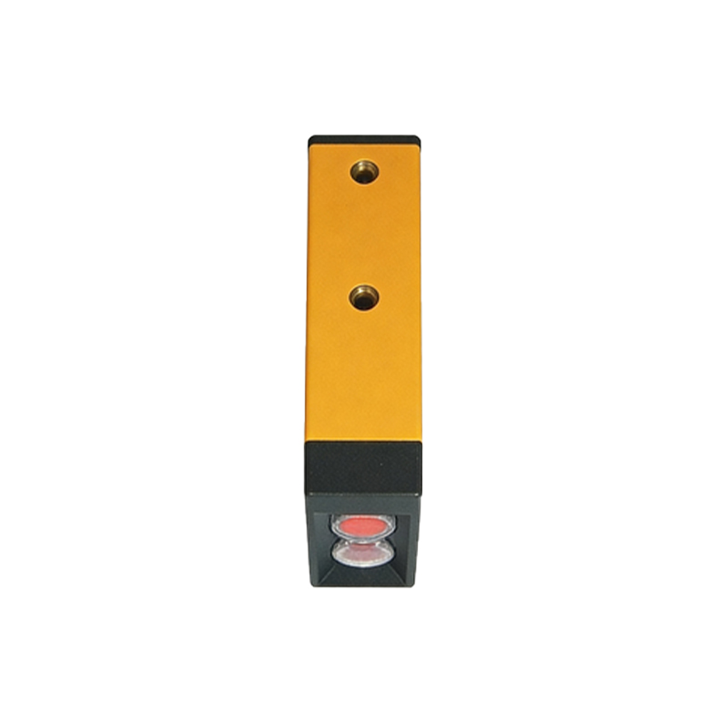
Tools and Materials Required
Gather the following: a compatible slot-type photoelectric sensor (with matching mounting dimensions), a small flathead screwdriver for terminal blocks, wire strippers, electrical tape or heat shrink tubing, a multimeter for continuity testing, and a cleaning solvent (like isopropyl alcohol) for the mounting area. For sensors with M8 or M12 connectors, a matching connector tool may be needed. Ensure the replacement sensor has the same slot width and response time to avoid false triggers.
Step 1: Remove the Old Sensor
First, disconnect the wiring. If using screw terminals, loosen the screws and carefully remove the wires, noting the color codes (brown for +V, blue for GND, black for output, white for optional test input). If using a connector, simply unplug it. Next, unscrew the mounting bolts or release the bracket clamps. Gently slide the sensor out from the mounting slot, being cautious of sharp edges. Clean the mounting area with solvent to remove debris and grease, which can affect the new sensor’s alignment.
Step 2: Install the New Sensor
Position the new sensor into the mounting bracket, ensuring it is flush and aligned with the target path. Tighten the mounting bolts to the manufacturer’s torque specification (typically 0.5–1.0 Nm for small brackets). Avoid overtightening, which can warp the housing. Connect the wires following the same color code: brown to positive power, blue to ground, and black to the load (e.g., PLC input). If the sensor has a test input, leave it disconnected unless needed for diagnostics. Use wire nuts or terminal blocks for secure connections, and wrap with electrical tape to prevent shorts.
Step 3: Align and Test the Sensor
Restore power to the system. Use a felt-tip marker or a small piece of cardboard to simulate a target passing through the slot. Observe the sensor’s LED indicator: it should illuminate when an object is detected, and turn off when the slot is clear. If the LED does not respond, adjust the sensor’s position slightly—check for lateral misalignment. Use a multimeter to measure the output voltage: for PNP sensors, the output should go high (near +V) when detecting; for NPN, it should go low (near 0V). Fine-tune the sensitivity potentiometer if present, but only after verifying proper alignment.
Step 4: Final Verification and System Integration
Run a full production cycle to confirm the sensor triggers correctly under load. Monitor the PLC input status via HMI or debugging software. Check for false triggers caused by vibrations or stray light. Tighten any loose connections and apply strain relief to the wiring. Document the replacement in the maintenance log, including the sensor model, install date, and any calibration settings. Finally, clean the lens of the new sensor with a lint-free cloth to ensure long-term reliability.
Troubleshooting Common Issues
If the sensor fails to work, first verify power supply voltage at the sensor terminals. A common issue is reversed polarity: blue and brown wires swapped. Check for damaged cables or loose connectors. If the LED is solid but no output, the sensor may be saturated by ambient light—add a shield or adjust the mounting angle. For intermittent detection, inspect the slot for debris or scratches. If the sensor has adjustable sensitivity, reduce it to avoid false triggers. In rare cases, a defective sensor may require replacement under warranty.