Introduction to Photoelectric Sensors
Photoelectric sensors are essential components in industrial automation, used for detecting objects, distances, and material presence through light beams. Over time, these sensors may require disassembly for maintenance, repair, or replacement. This guide provides a professional, step-by-step approach to safely and efficiently disassemble a standard photoelectric sensor, focusing on common types like through-beam, retro-reflective, and diffuse sensors. Always refer to the manufacturer’s datasheet before proceeding.
Safety Precautions and Tools Required
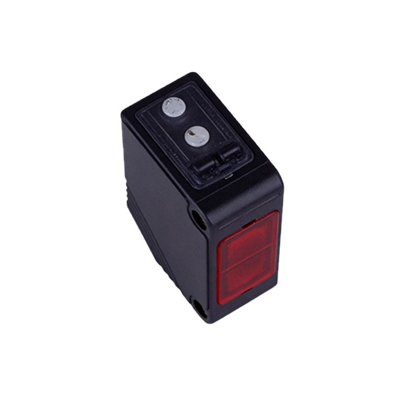
Before starting, ensure the sensor is disconnected from the power supply to prevent electrical shock or damage. Use appropriate personal protective equipment (PPE), such as safety glasses and anti-static wrist straps. Tools needed include a precision screwdriver set (Phillips and flathead), a small hex key set, tweezers, a multimeter for continuity checks, and a clean, well-lit workspace. Avoid excessive force to prevent cracking the sensor housing.
Step 1: Remove the Sensor from the Mounting Bracket
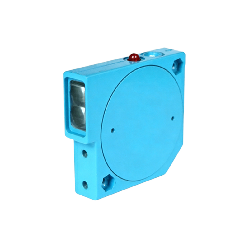
Locate the mounting bracket and screws securing the sensor. Use the appropriate screwdriver or hex key to loosen and remove these fasteners. Gently slide the sensor out of the bracket, being careful not to stress the cable or connector. If the sensor uses a quick-disconnect cable, detach it at the connector interface. Place the sensor on a non-marring surface.
Step 2: Disconnect the Cable and Connector
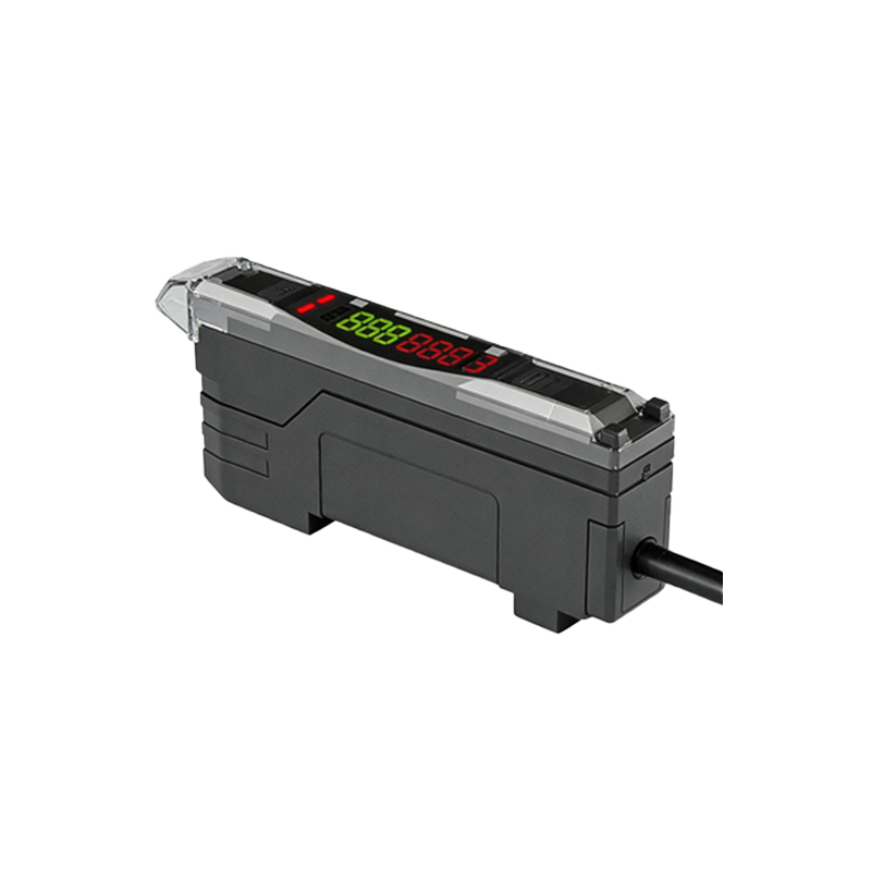
Inspect the cable entry point. For sensors with fixed cables, use a multimeter to identify and note wire colors for reassembly (e.g., brown for V+, blue for V-, black for output). For connectors (M12 or M8), unscrew the coupling nut by hand or with a wrench. Gently pull the connector away, avoiding cable strain. For soldered connections, desolder with a fine-tipped iron, taking care not to overheat the PCB.
Step 3: Open the Sensor Housing
Examine the housing for screws, clips, or adhesive seals. Common designs use a threaded front bezel or rear cap. Turn the bezel counterclockwise with a spanner wrench or by hand if knurled. If adhesive is present, apply gentle heat (e.g., heat gun at 60°C) to soften it. Carefully separate the housing halves using a plastic pry tool, starting from the seam. Avoid prying near the lens or electronics.
Step 4: Extract the Internal PCB Assembly
Once the housing is open, you will see the printed circuit board (PCB) with optical components (LED, phototransistor) and electronics. Use tweezers to lift the PCB gently from its slot, noting any alignment pins. Do not touch the lens or optical surfaces. If the PCB is secured with screws, remove them. For sensors with potting compound, use a Dremel tool or chisel to carefully remove the compound, but be aware this voids warranties.
Step 5: Remove the Lens and Optical Block
The lens is typically held by a retaining ring or glue. Rotate the ring counterclockwise with a lens spanner. If glued, apply isopropyl alcohol to dissolve the adhesive. Lift the lens with a suction cup or tweezers, being careful not to scratch it. Similarly, remove the optical block (if present) by unscrewing or unclipping. Clean the lens with a microfiber cloth and lens cleaner if reusing.
Step 6: Inspect and Troubleshoot Components
With the sensor fully disassembled, visually inspect the PCB for burnt components, cracked solder joints, or corrosion. Use a multimeter to test the phototransistor’s resistance (typically high in darkness, low in light). Check the LED with a diode test. Measure capacitors and resistors for deviations. This step helps identify failure points for repair or replacement.
Step 7: Reverse Process for Reassembly
To reassemble, follow the steps in reverse order. Apply thermal paste to any heat sinks, secure the PCB, replace the lens, and align the housing threads. Reconnect cables, ensuring correct polarity. Use a torque wrench for mounting screws (typically 0.5-1.0 Nm). Perform a functional test with a target object to verify sensitivity and response time. Calibrate as needed per manufacturer specs.
Common Issues During Disassembly
Engineers often encounter stuck screws due to threadlocker, seized O-rings, or hardened sealant. Use penetrating oil (e.g., WD-40) sparingly on threads. For stripped screws, use a screw extractor. If the housing is sealed with epoxy, consider that disassembly is destructive and may require a full replacement. Always document the process with photos for reference.
Conclusion and Best Practices
Proper disassembly of photoelectric sensors requires patience, precision, and adherence to safety protocols. Always keep a clean working environment to avoid contaminating optics. Label all removed parts and store them in a tray. If the sensor is under warranty, consider professional service to avoid voiding coverage. Regular maintenance and proper disassembly can extend sensor life and reduce downtime in industrial systems.