Understanding the Core Components of a Photoelectric Sensor Control Cabinet
A photoelectric sensor control cabinet is a critical assembly in modern industrial automation, housing the power supply, controllers, relays, and terminal blocks that interface with multiple photoelectric sensors. The control cabinet provides centralized management for sensor signals, ensuring reliable detection of objects, distances, and colors. Typically, the cabinet includes a PLC or dedicated sensor controller, status indicators, and surge protection devices. The layout prioritizes easy access for maintenance and efficient heat dissipation to prevent component failure. Proper grounding and shielding are essential to minimize electromagnetic interference, which can degrade sensor performance in harsh factory environments.
Key Wiring and Connection Strategies for Sensor Cabinets
When examining a photoelectric sensor control cabinet image, pay attention to the wiring organization. Color-coded cables for power (24V DC or 120V AC), signal outputs (NPN or PNP), and communication lines (IO-Link or Ethernet/IP) simplify troubleshooting. Terminal blocks should be clearly labeled with sensor IDs and functions, such as emitter, receiver, or diffuse reflection type. For multi-sensor systems, daisy-chaining power and using common return lines reduces wiring complexity. High-quality images often show DIN-rail mounted components, which allow modular expansion. Ensure that cable ducts or wireways separate high-voltage and low-voltage lines to avoid cross-talk.
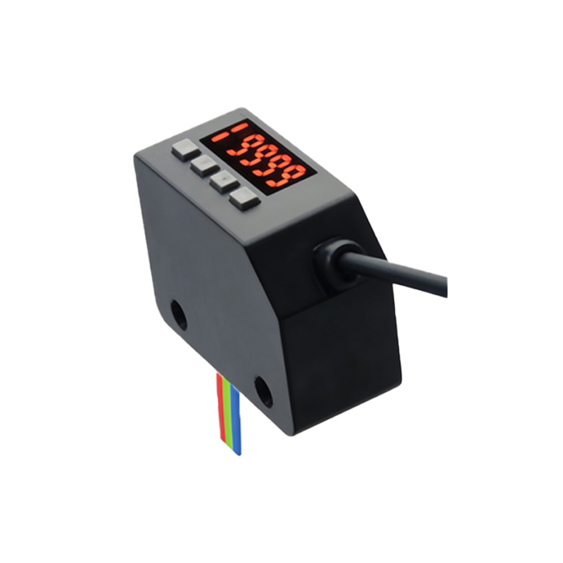
Typical Enclosure Types and Protection Ratings in Industrial Settings
Images of photoelectric sensor control cabinets frequently depict enclosures rated for specific environments. For washdown areas, stainless steel enclosures with IP66 or IP69K ratings prevent moisture ingress. In dusty workshops, NEMA 12 or IP54 cabinets with gasketed doors are standard. The cabinet material (polycarbonate, aluminum, or painted steel) influences durability and weight. Look for features like viewing windows for status LEDs, external disconnect switches for safety, and cable glands with proper strain relief. A well-designed image will illustrate how ventilation louvers or fans manage internal temperatures, especially when multiple sensors generate heat.
Common Troubleshooting Indicators Visible in Cabinet Photos
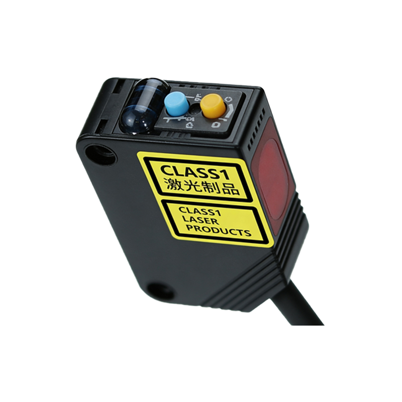
Experienced engineers can diagnose issues directly from a control cabinet image. Blinking LEDs on the sensor amplifier or PLC module often indicate alignment problems, contamination on the lens, or wiring faults. Check for loose terminal screws, burned fuses, or discolored relays caused by overcurrent. Images may also show diagnostic displays showing error codes or signal strength (e.g., 0-10V or 4-20mA). The placement of spare fuses and manuals inside the door is a good practice. If the cabinet shows excessive dust or corrosion on contacts, it suggests poor sealing or environmental exposure.
Best Practices for Mounting and Cable Entry in Sensor Cabinets
Proper mounting of a photoelectric sensor control cabinet ensures longevity. Images often highlight the use of vibration-dampening mounts near heavy machinery or robots. Cable entry should be from the bottom using liquid-tight connectors to prevent water dripping along wires into the cabinet. For wireless sensor networks, the cabinet may include antenna pass-throughs or external signal boosters. The image should demonstrate neat cable termination within the cabinet, using ferrule connectors on stranded wires to ensure secure connections in high-vibration environments. Labels on every cable and component comply with industrial standards like NFPA 79 or IEC 60204.
Future Trends: Smart Cabinets with Integrated Connectivity
Recent images show photoelectric sensor control cabinets evolving with IIoT capabilities. Embedded gateways collect sensor data for predictive maintenance, while touch screen HMIs replace traditional pushbuttons. Look for POE-powered sensors in the cabinet design, which simplify installation by eliminating separate power cables. Advanced cabinets feature modular I/O blocks that can be hot-swapped without powering down the system. The image might also show integrated surge arrestors for outdoor sensors, or fiber optic converters for long-distance communication. These innovations reduce downtime and improve operational flexibility in smart factories.