Introduction to N15 Photoelectric Sensor Circuits
The N15 photoelectric sensor is a widely used component in industrial automation, particularly for object detection, distance measurement, and position sensing. Its circuit design must ensure reliable performance under varying light conditions and environmental factors. This article explores the core circuit architecture, key components, and practical considerations for integrating N15 sensors into automated systems.
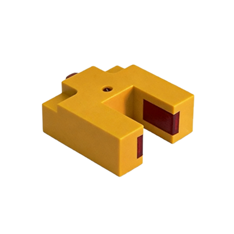
Core Circuit Architecture
The typical N15 sensor circuit consists of an emitter (LED) and a receiver (phototransistor or photodiode), combined with signal processing units. The emitter generates modulated infrared light, which is reflected or blocked by the target object. The receiver converts the optical signal into an electrical current, which is then amplified and filtered. A comparator circuit, such as an LM393, is often used to convert the analog signal into a clean digital output, triggering a logic high or low depending on the presence of the object.
Key Component Selection
For stable operation, select a high-frequency modulated LED (e.g., 850 nm or 940 nm) to reduce ambient light interference. The phototransistor should have a fast response time and high sensitivity. Use a low-noise operational amplifier (e.g., OP07) for signal conditioning. Resistors and capacitors in the feedback loop determine the gain and bandwidth. A voltage regulator (e.g., 7805) ensures stable power supply to the sensor module, especially in industrial environments with voltage fluctuations.
Signal Conditioning and Noise Reduction
Ambient light, electrical noise, and temperature drift can degrade sensor performance. Implement a bandpass filter tuned to the LED modulation frequency to reject DC light and low-frequency noise. Add a hysteresis circuit (using positive feedback) to the comparator to prevent output jitter when the object is near the detection threshold. Shielding the sensor housing and using twisted-pair cables for power and signal lines further reduces electromagnetic interference.
Practical Application Considerations
When designing the PCB layout, place the emitter and receiver close together for reflective sensing or separate them for through-beam applications. Ensure the optical path is free from dust or obstructions. Calibration is critical: adjust the potentiometer in the comparator circuit to set the detection distance and sensitivity. For harsh industrial environments, consider adding a protective lens and conformal coating to the circuit board.
Testing and Troubleshooting
After assembly, test the sensor with a known target at the expected distance. Use an oscilloscope to check the waveform at the receiver output; it should show a clear pulse train. If the output is unstable, verify the power supply ripple, re-check the filter component values, and ensure the LED driver circuit provides sufficient current (typically 20-50 mA). Common issues include false triggering due to reflective surfaces or insufficient beam intensity, which can be mitigated by adjusting the modulation frequency or using a lens.
Conclusion
The N15 photoelectric sensor circuit, when properly designed, offers robust and reliable detection for industrial automation. By focusing on component selection, signal conditioning, and environmental protection, engineers can achieve high accuracy and long-term stability. These circuits are essential for conveyor systems, packaging machines, and robotic positioning tasks.