Understanding the 4-Wire Photoelectric Sensor
A 4-wire photoelectric sensor is a common industrial component used for object detection. It typically consists of two power wires (VCC and GND) and two output wires (NO and NC, or PNP and NPN). Understanding the color code is critical: Brown for VCC (10-30V DC), Blue for GND, Black for normally open (NO) output, and White for normally closed (NC) output. This guide focuses on the PNP type, which is widely used in PLC and controller inputs.
Tools and Materials Needed
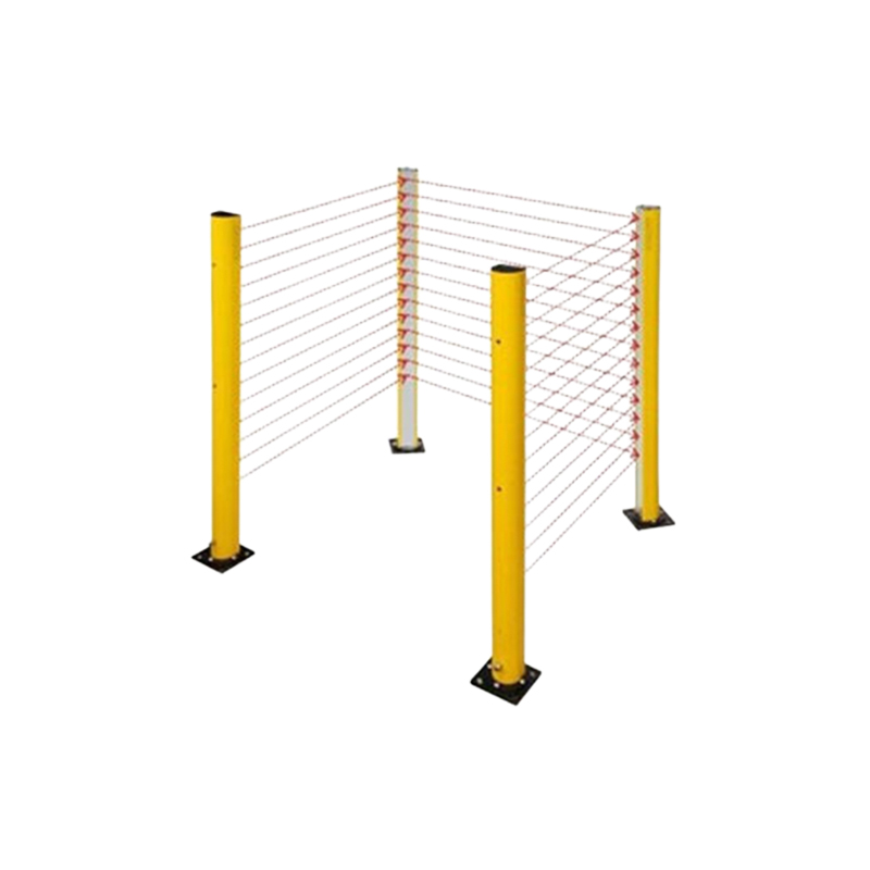
Before starting, gather the following tools: a screwdriver set, wire strippers, a multimeter, electrical tape, and heat shrink tubing. The 4-wire sensor itself, a controller or PLC, and a 24V DC power supply are essential. Ensure all equipment is de-energized during installation.
Step 1: Identify Sensor Wires
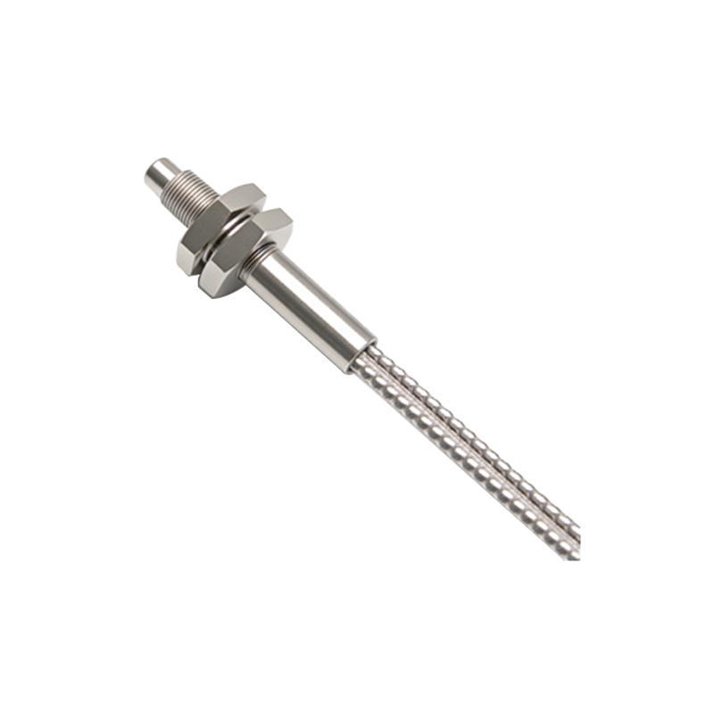
Check the sensor datasheet or label. For a standard 4-wire PNP sensor: Brown wire is positive (VCC), Blue is negative (GND), Black is the normally open output (active high when target is present), and White is the normally closed output (active low). Use a multimeter to verify continuity if needed.
Step 2: Connect Power Supply
Connect the Brown wire to the positive terminal of the 24V DC power supply. Connect the Blue wire to the negative terminal (GND). Ensure the power supply is stable and within the sensor’s voltage range (typically 10-30V DC). Use wire connectors or terminal blocks for secure connections.
Step 3: Wire the Outputs to Controller
For most applications, use the Black wire (NO) for object detection. Connect the Black wire to the input terminal of a PLC or relay. The White wire (NC) can be left unconnected if not used, but ensure it is insulated to avoid short circuits. If using the NC output, connect it to a separate input for fail-safe detection.
Step 4: Grounding and Shielding
Proper grounding reduces electrical noise. Connect the sensor’s shield (if present) to the system ground. For unshielded sensors, keep the sensor cable away from high-voltage lines. Use a ferrite core on the cable if interference is suspected.
Step 5: Test the Installation
Power up the system. Place a target object in front of the sensor. Use a multimeter to check voltage between the Black wire and GND: it should be 24V when the target is detected and 0V when not. Verify the white wire output is opposite. Adjust the sensor’s sensitivity pot if available.
Wiring Diagram Summary
Here is a simplified connection map: Brown to 24V+, Blue to GND, Black to PLC input, White to PLC input (optional). Ensure all connections are tight and use cable glands for protection in harsh environments. Always follow local electrical codes.