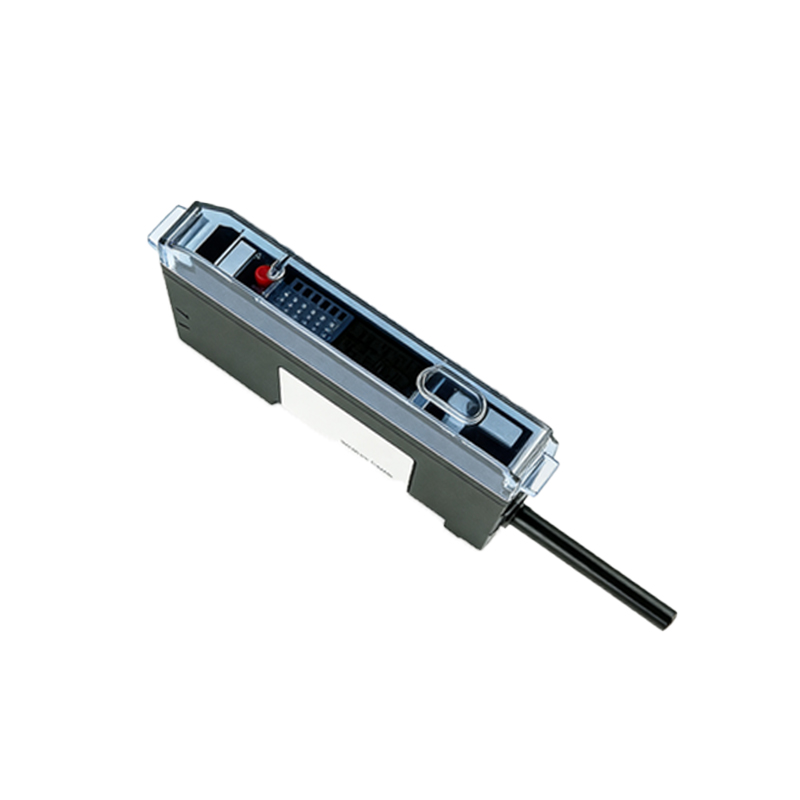
Introduction to Photoelectric Sensors in RPM Measurement
Photoelectric sensors are widely used in industrial automation for non-contact speed measurement of rotating machinery. These sensors detect the presence or absence of an object, such as a reflective mark or a rotating disc with slots, and convert optical signals into electrical pulses. The pulse frequency directly correlates with the rotational speed, typically measured in revolutions per minute (RPM). For electrical engineers, understanding the calculation process is essential for applications like motor speed monitoring, conveyor belt control, and turbine speed feedback.Sensor Types and Setup for RPM Calculation
Common photoelectric sensor configurations include through-beam, retro-reflective, and diffuse reflective types. For RPM measurement, a reflective sensor or a slotted disc is often used. For example, install a reflective tape on the rotating shaft and position a diffuse sensor to detect it. Alternatively, mount a slotted wheel between a through-beam pair. The key parameter is the number of pulses per revolution (PPR). If the wheel has N slots or marks, each revolution generates N pulses. Ensure the sensor response time is faster than the pulse period to avoid missed signals.Fundamental RPM Calculation Formula
The basic formula for RPM is:RPM = (Pulse Frequency in Hz × 60) / Pulses per Revolution (PPR)
To obtain pulse frequency, measure the time interval between consecutive rising edges using a microcontroller or PLC. For instance, if a sensor outputs 100 Hz and the disc has 4 slots, RPM = (100 × 60) / 4 = 1500 RPM. This straightforward calculation assumes a constant speed. For variable speeds, use an averaging method over multiple pulses to improve accuracy.
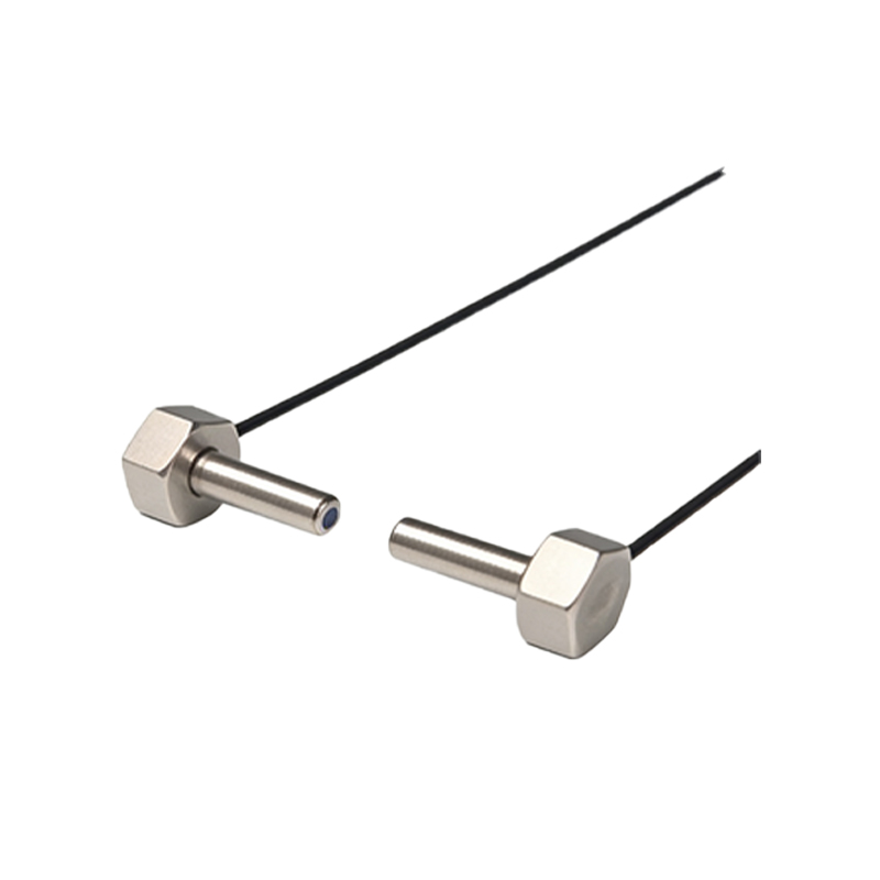
Practical Example with a Reflective Sensor
Consider a motor shaft with a single reflective mark. The sensor detects it once per revolution. If the measured pulse frequency is 25 Hz, then PPR = 1, so RPM = 25 × 60 = 1500 RPM. However, with only one mark, low-speed measurements may have low resolution. To enhance resolution, increase PPR by using a disc with multiple marks. For example, with 60 slots, each pulse corresponds to 60-degree rotation, providing finer speed granularity. Always account for sensor lag and ambient light interference in industrial environments.Handling Measurement Errors and Noise
Electrical noise and mechanical vibration can cause false pulses. Use Schmitt trigger circuits or software debouncing to filter out glitches. For high-speed applications, ensure the sensor's switching frequency exceeds the expected pulse rate. For instance, a sensor with 10 kHz bandwidth is suitable for up to 100,000 RPM with 6 PPR. Calibrate the system by comparing with a tachometer. Additionally, consider using shielded cables and proper grounding to minimize electromagnetic interference.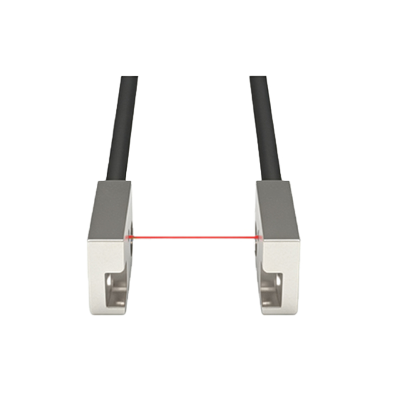
Advanced Techniques: Frequency-to-Voltage Conversion
For analog output, use a frequency-to-voltage converter like the LM2917. This chip outputs a DC voltage proportional to the input frequency. Connect the sensor pulse train to the input, and the output voltage can be read by an analog-to-digital converter. The formula becomes: Voltage = (RPM × K) / PPR, where K is the converter constant. This method is ideal for legacy control systems without digital counters.Conclusion and Best Practices
Accurate RPM measurement via photoelectric sensors relies on correct PPR selection, noise reduction, and proper calibration. Always validate the sensor's response time against the maximum expected RPM. For critical systems, implement redundant sensors or use encoder-based feedback. By mastering these calculations, electrical engineers can design robust speed monitoring systems for industrial automation.