Understanding Photoelectric Sensor Fundamentals
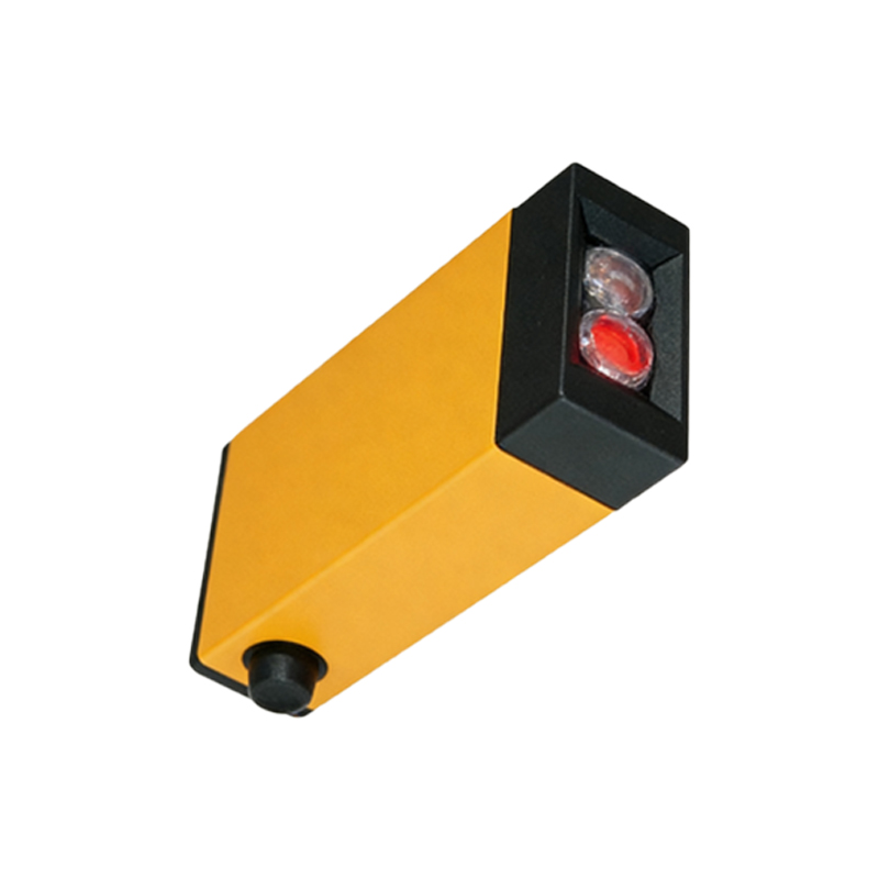
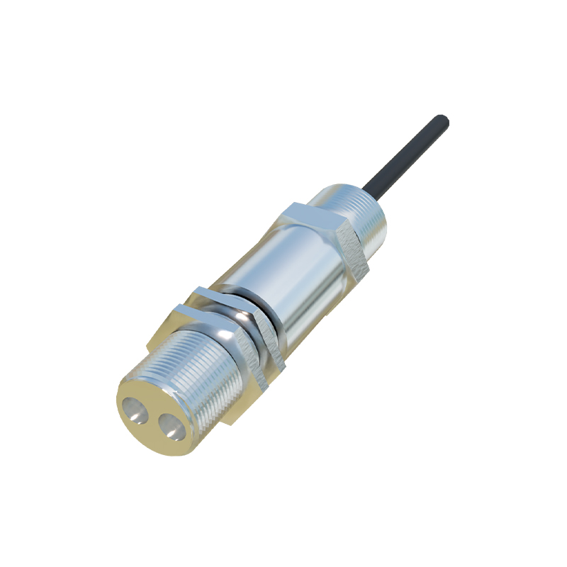
Photoelectric sensors are essential components in industrial automation, enabling non-contact detection and distance measurement through light emission and reception. As an electrical engineer, you must first grasp the three main types: through-beam, retro-reflective, and diffuse-reflective sensors. For distance measurement, diffuse-reflective sensors with time-of-flight (ToF) technology are commonly used, as they measure the time taken for a light pulse to travel to the target and back. Key parameters include sensing range, response time, and output type (analog or digital). Ensure your sensor datasheet specifies the measurement resolution, typically in millimeters, and the interface protocol, such as analog voltage (0-10V), current (4-20mA), or digital serial communication (I2C, SPI, or RS-232).
Selecting the Right Microcontroller and Interface
The program’s core relies on the microcontroller (MCU) chosen to process sensor data. For high-speed applications, use an ARM Cortex-M series MCU with built-in analog-to-digital converters (ADC) or hardware timers for pulse-width measurement. For ToF sensors like the VL53L0X or OPT3101, prefer MCUs supporting I2C or SPI communication. Circuit design must include decoupling capacitors near the sensor to minimize noise, and level-shifting circuits if the sensor operates at 3.3V while the MCU is 5V. Always verify the maximum clock frequency to avoid data corruption, and implement pull-up resistors on I2C lines for reliable communication.
Writing the Core Distance Measurement Algorithm
Start by initializing the sensor and MCU peripherals. For analog sensors, configure the ADC with a reference voltage matching the sensor output range. Example code snippet in C for a 0-10V analog sensor:
``c
#include
#include "stm32f4xx_hal.h"
ADC_HandleTypeDef hadc1;
uint32_t adc_value;
float distance;
void ReadSensor(void) {
HAL_ADC_Start(&hadc1);
if (HAL_ADC_PollForConversion(&hadc1, 100) == HAL_OK) {
adc_value = HAL_ADC_GetValue(&hadc1);
distance = (adc_value / 4095.0) * 100.0; // Assuming 12-bit ADC and 0-100cm range
}
HAL_ADC_Stop(&hadc1);
}
`
For digital ToF sensors, read the distance register via I2C and convert the raw data to millimeters. Include error handling for out-of-range readings or communication failures, and implement a median filter to smooth noisy measurements.
Optimizing Program Performance for Industrial Use
In production environments, response time and stability are critical. Use interrupt-driven ADC conversions instead of polling to free CPU cycles. For I2C sensors, enable DMA transfers to handle data without blocking the main loop. Implement a moving average filter with a window size of 5-10 samples to reduce jitter, and add a timeout mechanism to detect sensor disconnection. Example filter code:
`c
#define FILTER_SIZE 5
float buffer[FILTER_SIZE];
int index = 0;
float MovingAverage(float new_value) {
buffer[index] = new_value;
index = (index + 1) % FILTER_SIZE;
float sum = 0;
for (int i = 0; i< FILTER_SIZE; i++) sum += buffer[i];
return sum / FILTER_SIZE;
}
``
Additionally, calibrate the sensor by measuring known distances and adjusting the offset and gain in software. Store calibration constants in non-volatile memory (EEPROM) for persistent operation.
Integrating the Program with a Control System
Once the distance data is reliable, output it to a PLC or HMI via standard industrial protocols like Modbus RTU or analog signals. For serial communication, use a UART with RS-232 or RS-485 transceivers. Structure your program as a state machine to handle initialization, measurement, communication, and error states. Example Modbus function code to send distance as a 16-bit integer: write a holding register at address 40001. Ensure the baud rate matches the system, and include CRC checking for data integrity. Finally, test the system with a known moving target to validate accuracy and update rate.