Understanding the OBT300 Diffuse Photoelectric Sensor
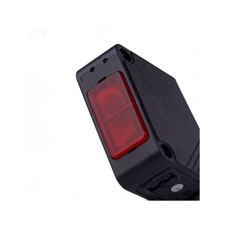
The OBT300 is a standard diffuse photoelectric sensor commonly used in industrial automation for object detection without a reflector. It emits a modulated infrared light beam and detects the reflected light from the target surface. As an electrical engineer, you must understand its wiring configuration to ensure reliable operation in harsh environments. The sensor typically operates on a 10-30 VDC supply and provides a PNP or NPN output, depending on the model variant. Correct wiring is critical to avoid false triggering, voltage drop, or damage to the sensor.
Color Code for OBT300 Wiring
Typical OBT300 sensors come with a 4-wire or 3-wire M12 connector. For a standard 4-wire PNP configuration: Brown wire connects to +VDC (10-30V), Blue wire connects to 0VDC (ground), Black wire is the normally open (NO) output, and White wire is the normally closed (NC) output. For NPN models, the Black and White wires serve as sinking outputs. Always verify the datasheet for your specific OBT300 variant, as color codes may vary by manufacturer (e.g., if using a Sick, Banner, or Omron version). Use a multimeter to confirm continuity before powering up.
Wiring Diagram for PNP and NPN Configurations
In a PNP configuration, the sensor outputs a positive voltage signal when an object is detected. Connect the Black wire to the input of a PLC or relay with a pull-down resistor. For NPN, the output sinks to ground when triggered, so connect the Black wire to a PLC input with a pull-up resistor. Below is a simplified wiring diagram: Power Supply +VDC (Brown) -> Sensor; Power Supply 0VDC (Blue) -> Sensor; Sensor Output (Black) -> Load/PLC Input. Ensure the load current does not exceed the sensor’s rated 100-200 mA.
Tips for Troubleshooting and Installation
Always use shielded twisted-pair cables to minimize electromagnetic interference (EMI) near motors or inverters. Verify the sensing distance (typically 10-30 cm for OBT300) and adjust the potentiometer if present. If the sensor triggers erratically, check for loose connections or voltage drop; ensure the supply voltage stays within 10-30 VDC. For long cable runs, consider adding a surge suppressor or using a 24 VDC regulated supply. Finally, test the wiring with a dummy load before integrating into the final automation system.