Introduction to Through-Beam Photoelectric Sensors
Through-beam photoelectric sensors, also known as opposed-mode sensors, are a fundamental component in industrial automation. They consist of two separate units: an emitter and a receiver. The emitter projects a continuous beam of light, typically infrared or visible red, directly at the receiver. When an object interrupts this beam, the sensor detects the change and triggers an output signal. This simple yet robust design ensures high reliability in harsh environments, making it ideal for long-range detection, dust-laden areas, and applications requiring precise object presence verification.
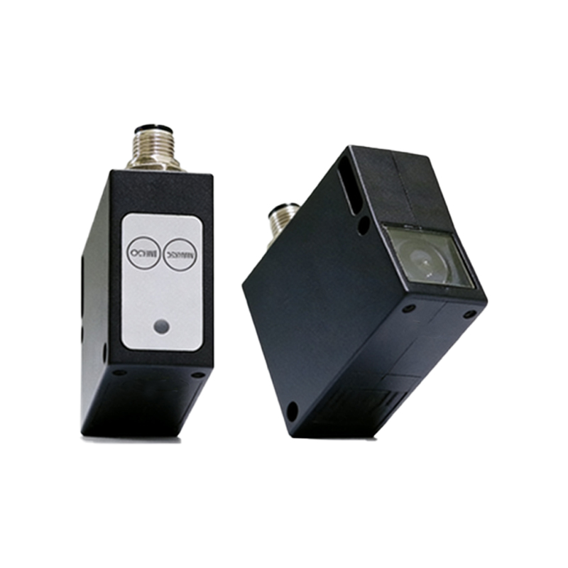
Emitter Unit: Light Source and Optics
The emitter unit houses a light source, often an LED (light-emitting diode) or a laser diode, depending on the required range and precision. The LED-based emitters are cost-effective and suitable for general-purpose use, with typical wavelengths around 850 nm to 950 nm for infrared or 660 nm for visible red. Laser emitters offer narrower beams, extending detection distances up to 100 meters. The optics in the emitter include a collimating lens that focuses the light into a parallel beam, minimizing divergence. This collimation is critical for maintaining beam integrity over long distances, reducing the risk of false triggers from ambient light or misalignment.
Receiver Unit: Photodetector and Signal Processing
On the opposite side, the receiver unit contains a photodetector, such as a photodiode or phototransistor, aligned directly opposite the emitter. The photodetector converts the received light intensity into an electrical current. Modern receivers integrate advanced signal processing circuits, including amplifiers and threshold comparators, to filter out noise from stray light or electromagnetic interference. A key feature is the use of modulated light. The emitter pulses the light at a specific frequency, and the receiver is tuned to this frequency, allowing it to discriminate between the sensor's beam and ambient light sources like sunlight or factory lighting. This modulation enhances stability in challenging conditions.
Housing and Lens Design
The housing of a through-beam sensor is typically constructed from rugged materials like stainless steel or reinforced plastic, rated with IP67 or higher for dust and water ingress protection. The lens material is often polycarbonate or glass, chosen for optical clarity and resistance to scratching or chemical exposure. The emitter and receiver units are housed in separate cylindrical or rectangular enclosures, each with mounting brackets for precise alignment. A critical aspect of the design is the alignment indicator, such as an LED or a mechanical sight, which helps technicians optimize the beam path during installation. Misalignment can cause detection failures, so adjustable mounting systems are common.
Electrical Interface and Output Configurations
The electrical interface in through-beam sensors varies by application. Common output types include NPN (sinking) and PNP (sourcing) transistor outputs, as well as relay or solid-state outputs for direct load control. The sensor operates on a DC voltage range, typically 10-30 VDC, with some models supporting AC or universal power supplies. The receiver's output goes high when the beam is uninterrupted and switches low when the beam is blocked, or vice versa, depending on the light-on/dark-on configuration. Many sensors feature built-in short-circuit protection, reverse polarity protection, and LED status indicators for quick diagnostics.
Alignment and Installation Considerations
Proper alignment is paramount for through-beam sensor performance. The emitter and receiver must be aligned along a common optical axis, with tolerances often within a few degrees. Installation typically involves mounting the units on opposite sides of a conveyor belt, machine opening, or passageway. To mitigate vibration effects, lock washers and rigid brackets are recommended. The beam path must be free of obstructions, and reflective surfaces nearby should be minimized to avoid false reflections. For long distances, laser alignment tools or visual indicators on the sensor housing simplify the setup process.
Applications and Advantages
Through-beam sensors excel in applications requiring long detection ranges, such as 10 to 100 meters, and in environments with heavy dust, fog, or smoke where diffuse sensors would fail. Common uses include counting objects on high-speed conveyors, detecting vehicle presence at warehouse doors, and ensuring safety in automated machinery. The primary advantage is high reliability due to the direct beam path, which is less susceptible to background interference. However, the separation of emitter and receiver increases wiring complexity and installation space requirements, making them less suitable for compact or cost-sensitive applications.
Conclusion
Understanding the structure of through-beam photoelectric sensors—from the emitter’s collimated light source to the receiver’s modulated signal processing—enables engineers to select and integrate these devices effectively. Their robust design and long-range capability make them indispensable in industrial automation, despite the need for careful alignment. As technology advances, laser-based emitters and smart sensors with IO-Link communication are expanding their functionality, further solidifying their role in modern manufacturing.