Understanding the S7-200 PLC Input Module
The Siemens S7-200 PLC is a compact and widely used controller in industrial automation. Its digital input modules typically operate at 24V DC, sourcing or sinking depending on the model. For most applications, the S7-200 CPU 22x series supports sink input logic (PNP sensors) by default, with the common terminal M connected to 0V. The input points (I0.0, I0.1, etc.) are designed to accept a positive signal from a sensor. When wiring a photoelectric sensor, you must match its output type to the PLC input configuration to avoid damage or unreliable readings.
Selecting the Right Photoelectric Sensor Type
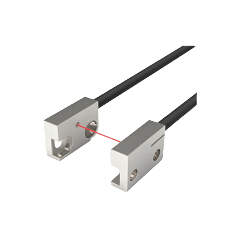
Photoelectric sensors come in three main output types: NPN (current sinking), PNP (current sourcing), and push-pull. For the S7-200, PNP sensors are the most straightforward choice because they output a positive 24V signal when triggered. If you use an NPN sensor, you will need to modify the wiring or add a pull-up resistor, as the PLC input expects a positive voltage. Always verify the sensor datasheet for output voltage, current rating, and response time to ensure compatibility with the S7-200 input specifications (typically 4 mA at 24V).
Wiring Diagram for PNP Sensor to S7-200
Connect the PNP photoelectric sensor as follows: the brown wire to +24V DC power supply, the blue wire to 0V (ground), and the black signal wire to the PLC input terminal (e.g., I0.0). Ensure the sensor's load resistor is internal or added externally if needed. On the S7-200 side, connect the 24V DC power supply to the L+ and M terminals on the CPU module. The common terminal for inputs (1M or 2M depending on the group) must be tied to 0V. This setup allows the sensor to pull the input high when detecting an object.
Wiring Diagram for NPN Sensor to S7-200
NPN sensors require a different approach. Connect the brown wire to +24V, the blue wire to 0V, and the black signal wire to the PLC input. However, since the S7-200 input expects a positive signal, you must configure the input group as source logic (if supported) or add a pull-up resistor (typically 2.2kΩ to 10kΩ) between the input terminal and +24V. Alternatively, use an external relay to invert the signal. The 1M or 2M terminal should be connected to +24V for sink input configuration, but this is less common and may require changing the PLC wiring scheme.
Checking Power Supply and Grounding
A stable 24V DC power supply is critical for both the PLC and the sensor. Use a dedicated industrial power supply rated at least 20% above the total load. Connect the power supply negative to the PLC M terminal and the sensor blue wire. Ensure proper grounding to avoid noise interference: connect the power supply chassis ground to the panel earth, and keep sensor signal cables away from high-voltage lines. For long cable runs, use shielded twisted-pair cable and connect the shield to earth at the PLC end only.
Testing and Troubleshooting the Connection
After wiring, power up the system and check the sensor LED indicator. If the sensor is active, the PLC input LED for the corresponding channel (e.g., I0.0) should light up when the sensor detects an object. Use the S7-200 programming software (STEP 7-Micro/WIN) to monitor the input status in the status chart. Common issues include reversed polarity, incorrect common terminal connection, or insufficient sensor output current. If the input does not respond, measure voltage at the input terminal (should be near 24V when active) and verify continuity.