Introduction to Photoelectric Sensors
Photoelectric sensors are non-contact devices widely used in industrial automation to detect the presence, absence, or distance of objects. They operate based on the principle of light emission and reception, converting optical signals into electrical outputs. These sensors are essential in applications ranging from conveyor belt monitoring to packaging line control.
Key Components and Light Source
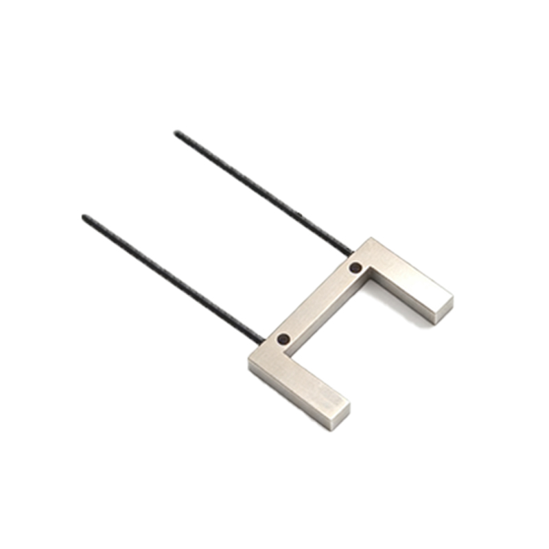
A typical photoelectric sensor consists of an emitter (light source), a receiver (photodetector), and a signal processing unit. The emitter generates a focused beam of light, often using an LED (light-emitting diode) or laser diode for high accuracy. The receiver is a phototransistor or photodiode that converts incoming light into an electrical current.
Emission and Modulation of Light
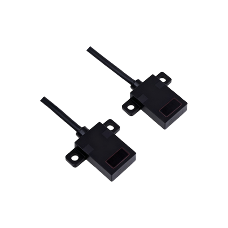
The emitter sends out a modulated light beam to minimize interference from ambient light sources. Modulation involves pulsing the light at a specific frequency, allowing the receiver to filter out noise from sunlight or artificial lighting. This ensures reliable detection in harsh industrial environments.
Detection Modes: Through-Beam, Retro-Reflective, and Diffuse
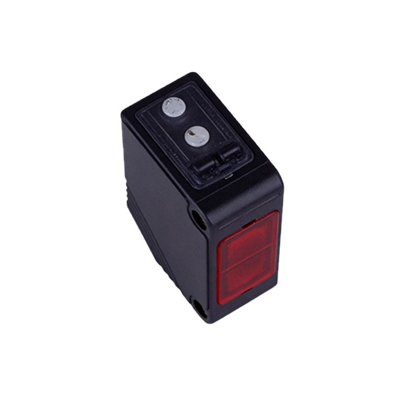
The workflow varies by detection mode. In through-beam mode, the emitter and receiver are separate; the object breaks the light path. Retro-reflective mode uses a reflector to bounce light back to the receiver; an object interrupts the beam. Diffuse mode relies on the object reflecting light directly to the receiver; the sensor triggers when sufficient light returns.
Signal Reception and Processing
When the receiver detects the reflected or interrupted light, it generates a change in the electrical signal. The processing unit amplifies this signal and compares it to a preset threshold. If the signal exceeds or drops below the threshold, the sensor outputs a binary or analog signal to a programmable logic controller (PLC) or control system.
Output and Integration into Control Systems
The final step involves transmitting the output signal. Common outputs include NPN (sinking) or PNP (sourcing) transistor switches, as well as analog voltage or current signals. Some sensors feature IO-Link for digital communication. The output triggers actuators, alarms, or data logs, enabling real-time process control.
Conclusion and Practical Considerations
Understanding the workflow of photoelectric sensors is crucial for proper selection and installation. Factors such as sensing distance, object color, and environmental conditions (dust, moisture) influence performance. By mastering these principles, engineers can optimize sensor placement and reduce downtime in automated systems.