Understanding the Counter Function in Automation
In industrial automation, counters are essential for monitoring production rates, batch processing, and inventory control. Photoelectric sensors are ideal for non-contact counting due to their reliability in harsh environments. When designing a counter system, the key is to ensure consistent detection of objects passing through the sensor’s beam. The sensor acts as a trigger, sending a pulse to a PLC or dedicated counter module. For accurate counting, consider object size, speed, and material. For example, a retro-reflective sensor works well for transparent objects, while a through-beam sensor offers high precision for small or fast-moving items.
Selecting the Right Photoelectric Sensor Type
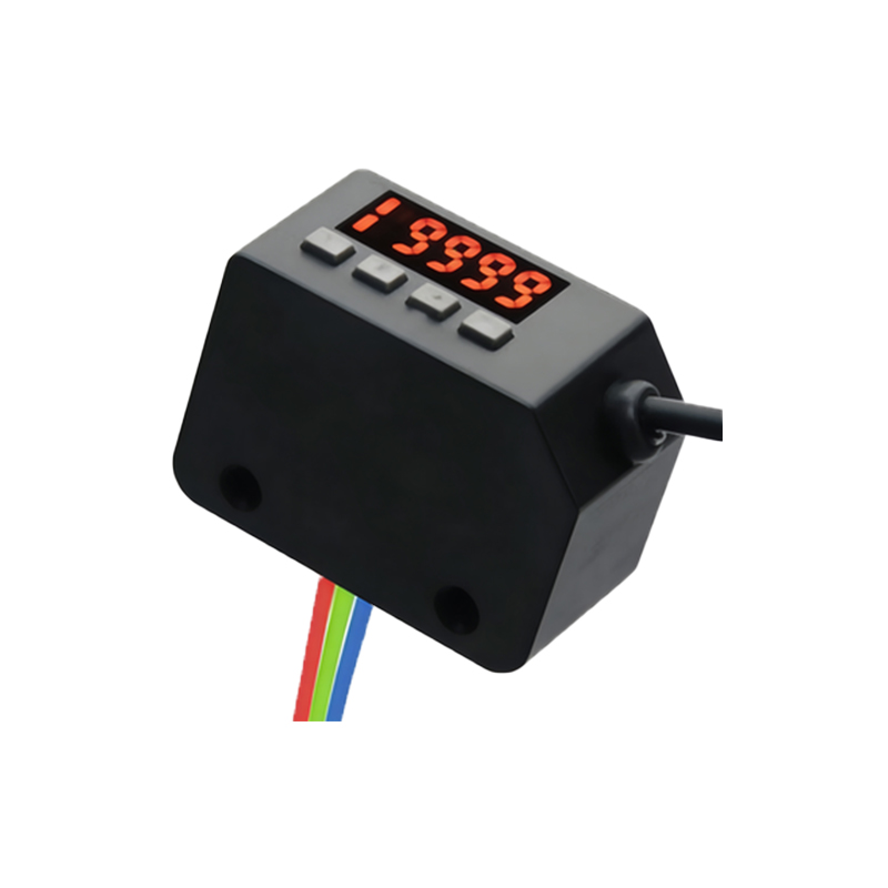
The choice of sensor depends on the application’s specific requirements. Through-beam sensors consist of separate emitter and receiver, providing the longest range and highest accuracy, but require alignment. Retro-reflective sensors use a reflector and are simpler to install, ideal for opaque objects. Diffuse sensors detect objects directly but have limited range and are sensitive to background interference. For counting, prioritize sensors with fast response times, such as those under 1 ms, to avoid missing fast-moving targets. Additionally, consider environmental factors like dust, moisture, or ambient light, which may require sensors with modulated light or immunity to stray light.
Configuring the Sensor for Pulse Output
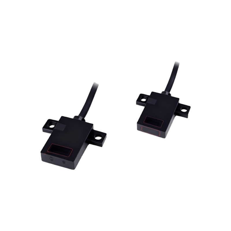
Most photoelectric sensors output a digital signal (NPN or PNP) that transitions when an object is detected. To design a counter, connect this output to a PLC input configured as a high-speed counter or a standalone counter module. Ensure the sensor’s switching frequency matches the expected object rate. For example, if objects pass at 100 per second, the sensor must support at least 100 Hz. Calibrate the sensitivity to avoid false triggers from dust or reflections. Use a timer or debounce circuit in software to filter out noise, especially in vibrating environments. For critical applications, implement a latch or reset function to handle startup conditions.
Integrating Sensors with PLCs and HMI
Integration involves wiring the sensor to a PLC input and programming the counter logic. In ladder logic, use a rising-edge trigger to increment a register each time the sensor activates. Set up a reset button or automatic reset after a predefined count, such as after 1000 units for batch control. Display the count on a Human-Machine Interface (HMI) for operator visibility. For high-speed counting exceeding 10 kHz, consider dedicated counter modules or microcontrollers with hardware counters. Test the system with actual objects to ensure the sensor’s dead zone (minimum gap between objects) is respected to avoid undercounting.
Addressing Common Design Challenges
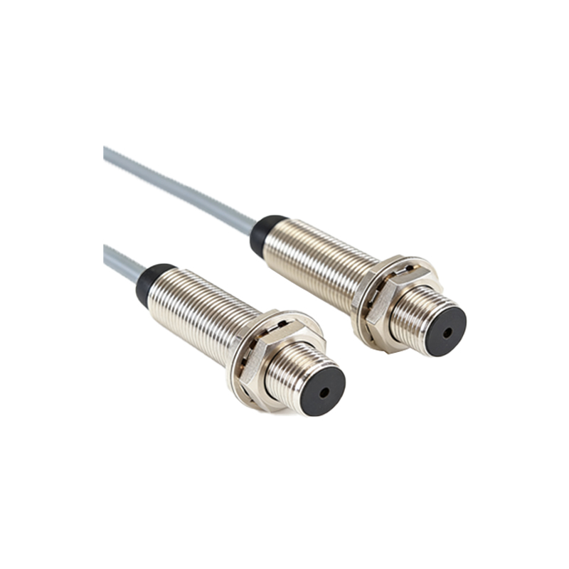
Common issues include double counting due to object reflections or sensor oscillation. To mitigate, adjust the sensor’s hysteresis or use a dark-on/light-on mode that matches the application. For transparent or shiny objects, use a polarized retro-reflective sensor to reduce false triggers. If the conveyor belt speed varies, use a sensor with a wide detection angle. For extreme environments, such as high temperatures or corrosive chemicals, select sensors with IP67 or higher ratings and stainless steel housings. Always document the sensor’s timing characteristics, such as response time and repeatability, to validate the design.
Testing and Calibration for Reliable Counting
After installation, perform a systematic test. Place objects at varying speeds and distances to verify count accuracy. Use a logic analyzer or oscilloscope to check the sensor’s output waveform for glitches. Calibrate the sensor’s threshold using a teach-in function if available. For example, adjust the sensitivity to detect the smallest object while ignoring background. Run a 24-hour stress test with simulated production to ensure stability. Record the count error rate—ideally below 0.01% for industrial standards. Update the PLC program with alarms for sensor faults, such as output stuck high or low.