Introduction to Photoelectric Pulse Measurement
Photoelectric sensors, also known as optical sensors, are widely used in industrial and medical applications to measure pulse rates. The principle relies on detecting changes in light absorption or reflection caused by blood volume variations in tissue. For electrical engineers, understanding the underlying optoelectronic mechanisms is crucial for designing accurate and reliable pulse measurement systems.
Working Principle: Photoplethysmography (PPG)
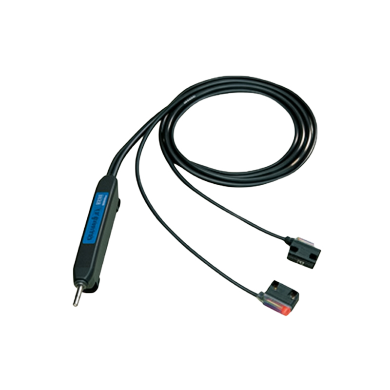
The core technique is photoplethysmography (PPG). A light-emitting diode (LED) emits light, typically in the red or infrared spectrum, onto the skin. A photodetector, such as a photodiode, captures the reflected or transmitted light. As blood pulses through arteries, the volume of blood changes, altering the amount of light absorbed. These variations produce a periodic signal corresponding to the heartbeat, which can be processed to extract pulse rate.
Sensor Types: Transmissive vs. Reflective
Two main configurations exist. In transmissive mode, the LED and photodetector are placed on opposite sides of a thin body part, like a fingertip, measuring light passing through. Reflective mode places both components on the same side, detecting backscattered light from deeper tissues. Reflective sensors are more versatile for wearable devices but require careful optical isolation to avoid direct light leakage.
Circuit Design Considerations
Engineers must address noise and signal integrity. The PPG signal is weak (microvolt to millivolt level) and susceptible to ambient light interference. A transimpedance amplifier (TIA) with high gain and low noise is essential. Use a bandpass filter (typically 0.5 Hz to 5 Hz) to eliminate DC drift and high-frequency noise. Shielding and proper grounding are critical to minimize electromagnetic interference (EMI).
Signal Processing for Pulse Detection
After analog conditioning, the signal is digitized via an ADC. Pulse detection algorithms, such as peak detection or autocorrelation, are implemented on a microcontroller or DSP. A moving average filter smooths the signal. The inter-beat interval (IBI) is calculated from consecutive peaks, and heart rate is derived as 60/IBI. Adaptive thresholding improves accuracy under motion artifacts.
Motion Artifact Mitigation
Motion artifacts are a major challenge. Techniques include using accelerometers to detect movement and apply adaptive filtering, such as the normalized least mean squares (NLMS) algorithm. Differential sensing with dual-wavelength LEDs (e.g., green and infrared) can also reduce motion noise by exploiting different penetration depths.
Practical Implementation Tips
Select LEDs with high radiant intensity and photodiodes with fast response times. For reflective sensors, maintain a fixed distance between LED and photodetector (typically 3-8 mm) to optimize signal. Use a mechanical housing to block ambient light. Calibrate the system with a known pulse generator. Test under various conditions, such as different skin tones and motion levels, to ensure robustness.