Introduction to Photoelectric Sensor Connections
Photoelectric sensors are essential components in industrial automation, providing non-contact object detection through light beams. Understanding their wiring diagrams is crucial for proper installation and operation. This guide covers common connection types, wire color codes, and practical diagram examples for through-beam, retro-reflective, and diffuse reflective sensors.
Basic Wiring Components and Color Codes
Standard photoelectric sensors typically feature three or four wires for power and signal. The common color code includes brown for positive DC voltage (10-30V DC), blue for negative or ground (0V), black for normally open (NO) output, and white for normally closed (NC) output. In AC sensors, two wires are common with brown and blue for line and neutral. Always verify with the manufacturer datasheet, as variations exist.
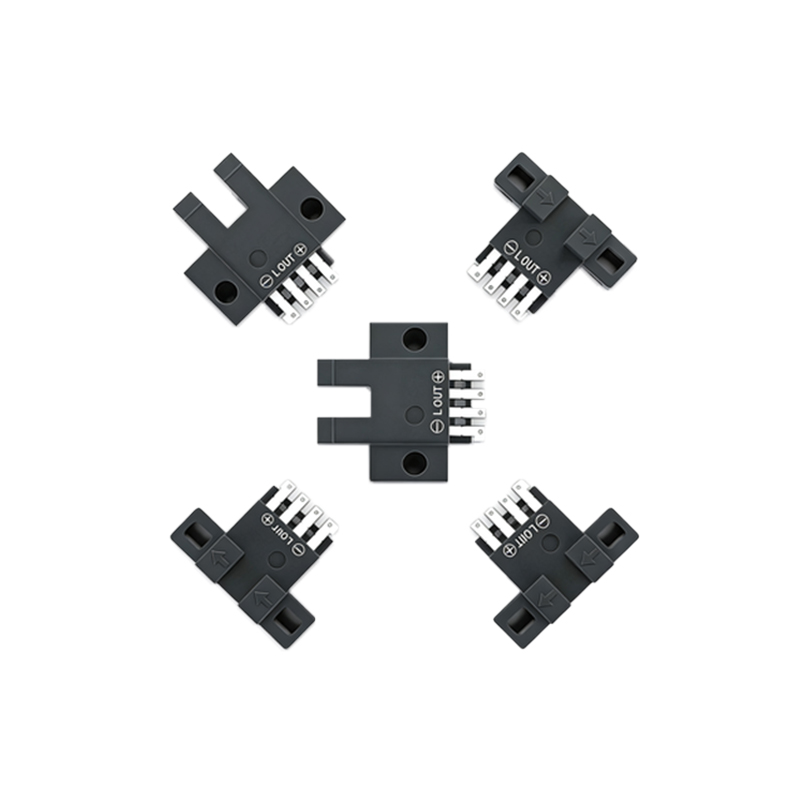
Through-Beam Sensor Connection Diagram
Through-beam sensors consist of separate emitter and receiver units. The emitter has two wires: brown to power supply positive and blue to ground. The receiver typically has three wires: brown to power, blue to ground, and black as the output signal. For a typical PNP (sourcing) output, the black wire connects to the PLC input module. When the light beam is interrupted, the output switches state, triggering the connected device.
Retro-Reflective Sensor Wiring Example
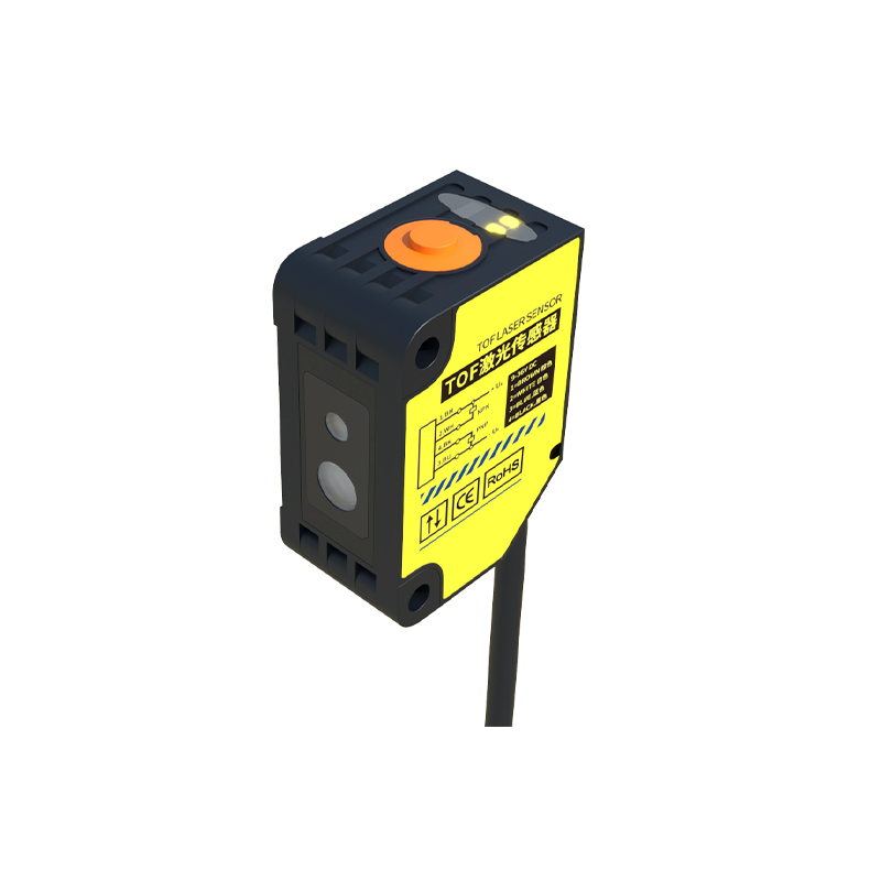
Retro-reflective sensors combine emitter and receiver in one housing, requiring a reflector. Wiring is similar to a three-wire sensor: brown to 24V DC, blue to 0V, and black as the NO output. Some models include a white wire for NC output or alarm. For example, in a conveyor system, connect the black wire to a relay coil; when the reflector is blocked, the output activates the relay. A typical diagram shows the sensor’s M12 connector with pin assignments: pin 1 (brown), pin 2 (white), pin 3 (blue), and pin 4 (black).
Diffuse Reflective Sensor Connection with Load
Diffuse reflective sensors detect objects by light reflection off the target itself. Wiring follows the same three-wire standard. For a NPN (sinking) output version, the black wire connects to the load (e.g., a PLC input) and the load returns to the power supply positive. In a practical setup, the sensor’s brown wire connects to +24V, blue to 0V, and black to a PLC digital input. When an object is within range, the output goes low (0V), signaling detection.
Wiring for Analog Output Photoelectric Sensors
Some advanced photoelectric sensors offer analog outputs (4-20 mA or 0-10V). These sensors have four or five wires: two for power and two for signal. For a 4-20 mA sensor, brown and blue are for power, and black (output+) and white (output-) connect to the analog input module. A sample diagram shows the black wire to AI+ and white to AI- on the PLC. Ensure proper shielding to avoid noise.
Troubleshooting Common Connection Issues
Connection errors often result from wrong wire color codes, incorrect supply voltage, or mismatched output types (PNP vs. NPN). Always confirm the sensor’s datasheet and use a multimeter to check voltage between brown and blue (should read 10-30V DC). For intermittent detection, verify that the load impedance matches the output rating. A typical troubleshooting diagram highlights checking the sensor’s LED indicator and signal voltage at the PLC input.
Safety and Installation Best Practices
When wiring photoelectric sensors, use appropriate cable glands and avoid bending wires sharply. Ensure power is off during connection. For outdoor or harsh environments, use shielded cables and proper grounding. Label all wires according to the diagram to simplify maintenance. Always test the system with a known object before full operation.