Understanding the Basics of Two-Wire Photoelectric Sensors
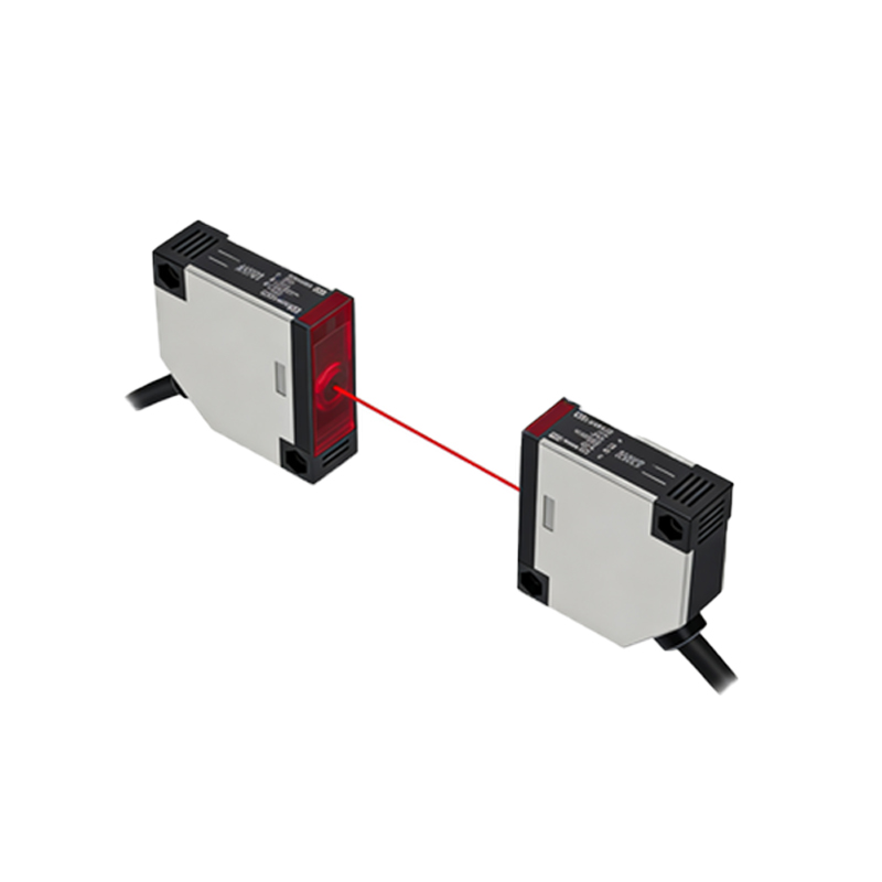
Two-wire photoelectric sensors are widely used in industrial automation for their simplicity and cost-effectiveness. Unlike three-wire sensors, which require separate power and signal lines, two-wire sensors integrate power and signal into a single pair of wires. This design reduces cabling complexity and is ideal for retrofitting existing systems. However, proper wiring is critical to avoid malfunction or damage. The sensor operates by modulating current flow on the loop to indicate detection, typically using a normally open (NO) or normally closed (NC) configuration. Ensure the load impedance matches the sensor’s specifications to maintain reliable performance.
Required Tools and Safety Precautions
Before wiring, gather essential tools: a multimeter for continuity testing, wire strippers, screwdrivers, and appropriate connectors. Adhere to safety protocols: disconnect power to the circuit, verify absence of voltage using a multimeter, and wear insulated gloves. For industrial environments, use cables with adequate insulation rating (e.g., PVC or PUR) to withstand mechanical stress and temperature variations. Confirm the sensor’s operating voltage range (e.g., 10-30 VDC) aligns with your power supply to prevent overvoltage damage.
Step-by-Step Wiring Procedure for Two-Wire Sensors
1. Identify the two wires: typically brown (positive) and blue (negative) for DC sensors, or brown and black for AC models. Refer to the datasheet for polarity.
2. Connect the brown wire to the positive terminal of the power supply through the load (e.g., PLC input module or relay coil). For NO configuration, the sensor closes the circuit upon detection; for NC, it opens.
3. Connect the blue wire directly to the negative terminal of the power supply. Ensure the load is placed in series with the positive line, not across the sensor, to maintain proper current loop.
4. Test the circuit: apply power and verify the sensor’s output by triggering the target. Use a multimeter to measure voltage drop across the sensor (typically<2 VDC when ON) and current leakage (<0.8 mA when OFF).
5. Secure all connections with terminal blocks or solder joints, and shield cables if running near high-voltage lines to prevent electromagnetic interference.
Common Wiring Mistakes and Troubleshooting
A frequent issue is incorrect load placement, which can cause the sensor to fail to switch or draw excessive current. For example, connecting the load in parallel with the sensor may result in continuous power draw. Another common error is mismatching polarity, leading to no output or permanent damage. Use a multimeter to check for short circuits or open connections. If the sensor does not detect, verify the target material and distance (refer to sensing range). For intermittent faults, inspect for voltage fluctuations or loose terminals. Always consult the manufacturer’s wiring diagram for model-specific nuances.
Application Considerations for Industrial Environments
In harsh settings, such as dusty or wet areas, use sensors with IP67 or higher ratings and ensure cable glands are tightened. For long cable runs (over 100 meters), account for voltage drop by increasing wire gauge (e.g., AWG 18 or larger). Two-wire sensors are commonly used in conveyor systems, object counting, and packaging machinery due to their easy integration with PLCs. However, they have limited current output (typically<100 mA), so avoid driving high-power loads directly. Use a relay or solid-state switch for such cases. Finally, test the system under full load conditions to validate stability.