Introduction to Infrared Photoelectric Sensor Ports
Infrared photoelectric sensors are critical components in industrial automation, used for object detection, proximity sensing, and position monitoring. The sensor port, often referred to as the connector interface, plays a vital role in ensuring reliable signal transmission and power supply. As an electrical engineer, understanding the standard port types, wiring configurations, and environmental considerations is essential for system integration and troubleshooting. Common port standards include M8, M12, and RJ45 connectors, each designed for specific application requirements such as IP ratings or data transmission speeds.
Key Port Types and Their Applications
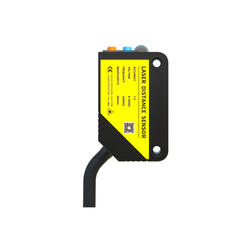
The most prevalent port types for infrared photoelectric sensors are M8 and M12 circular connectors, typically with 3 to 5 pins. M8 connectors are compact and suitable for space-constrained environments, while M12 connectors offer higher durability and are standard in industrial Ethernet protocols like IO-Link. For high-speed data applications, RJ45 ports with shielded cables are used. Additionally, some sensors feature integrated pigtail cables with pre-wired connectors, reducing installation complexity. Selecting the correct port type depends on factors like cable length, environmental exposure, and required communication protocol.
Wiring and Pinout Considerations
Proper wiring is crucial for sensor performance. Most photoelectric sensors use a 4-pin configuration: pin 1 (brown) for power supply (typically 10-30 VDC), pin 2 (white) for normally open (N.O.) output, pin 3 (blue) for ground, and pin 4 (black) for normally closed (N.C.) output or alarm. For IO-Link sensors, pin 4 doubles as a data communication line. Engineers must ensure correct polarity and avoid overcurrent conditions. Shielded cables are recommended for high-frequency noise environments, with the shield connected to the sensor housing or designated ground pin.
Environmental Protection and Port Sealing
Infrared sensor ports require proper sealing to withstand dust, moisture, and chemical exposure. IP67-rated connectors offer protection against temporary immersion, while IP69K is suitable for high-pressure washdown zones. Stainless steel or nickel-plated brass housings provide corrosion resistance. Engineers should also consider the use of protective caps when ports are not connected, and verify that cable glands maintain seal integrity. For outdoor or harsh industrial settings, UV-stabilized materials and vibration-resistant locking mechanisms are recommended.
Troubleshooting Common Port Issues
Common port-related problems include intermittent signal loss due to loose connections, pin corrosion from moisture ingress, or cable damage from mechanical stress. A systematic approach involves checking the connector torque—M12 connectors should be tightened to 0.6 Nm—and inspecting for bent pins or damaged o-rings. Using a multimeter to verify voltage at the sensor side and continuity across the cable can isolate faults. In IO-Link systems, check the port configuration in the master device to ensure proper data mapping. Regular maintenance, such as cleaning connectors with isopropyl alcohol, extends port lifespan.