1. Product Overview and Key Features
The ST150 photoelectric sensor is a high-performance industrial device designed for precise object detection in automation, packaging, and material handling systems. It operates using a modulated infrared light source, ensuring immunity to ambient light interference. Key features include a detection range of up to 15 meters, IP67-rated housing for harsh environments, and multiple output configurations (NPN/PNP). Its compact design allows for easy mounting in confined spaces, while the built-in indicator LED provides real-time status feedback. This sensor is ideal for applications requiring reliable detection of opaque, transparent, or reflective objects, even in dusty or wet conditions.
2. Technical Specifications and Electrical Parameters
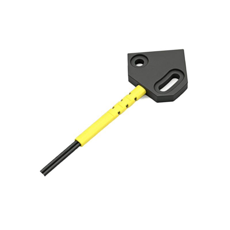
Understanding the technical specifications is critical for optimal performance. The ST150 operates on a supply voltage of 10-30V DC, with a maximum current consumption of 30mA. It offers a response time of less than 1ms, ensuring high-speed detection. The output type can be selected between NPN (normally open) or PNP (normally closed) via the internal wiring. The sensing distance is adjustable using a 270-degree potentiometer, located under the protective cap. The sensor’s operating temperature range is -25°C to +60°C, making it suitable for both cold storage and heated industrial environments. For electrical safety, the unit includes reverse polarity and short-circuit protection.
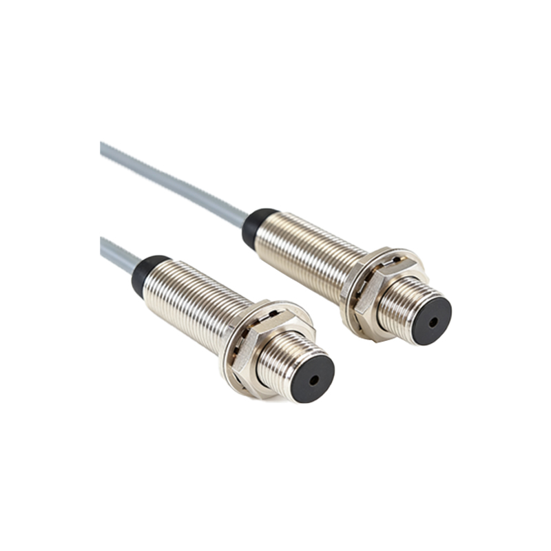
3. Installation and Mechanical Mounting
Proper installation ensures long-term reliability. Begin by selecting a mounting location free from excessive vibration and direct sunlight. Use the included M18 threaded bracket for secure fixing. Align the sensor’s optical axis perpendicular to the target object’s surface. Avoid mounting near reflective surfaces that could cause false triggers. The cable length is 2 meters, with a standard M12 connector for easy replacement. For through-beam models, ensure the emitter and receiver are aligned within 2 degrees of tolerance. Torque the mounting nut to 1.5 Nm to prevent loosening from machinery vibrations.
4. Wiring and Electrical Connections
Follow these wiring steps to avoid damage. Connect the brown wire to the positive terminal (+10-30V DC) and the blue wire to ground (0V). The black wire is the output signal; connect it to the PLC or control system input. For NPN output, the load should be connected between the output and the positive supply. For PNP output, connect the load between the output and ground. Do not exceed the maximum switching current of 100mA. Use shielded cable for long runs exceeding 10 meters to reduce electromagnetic interference. After wiring, verify the power LED lights up solid green.
5. Configuration and Sensitivity Adjustment
Calibrate the sensor for your specific application. Rotate the sensitivity potentiometer clockwise to increase detection range, counterclockwise to reduce it. For transparent objects, start with medium sensitivity and fine-tune until stable detection is achieved. Use a test target—a standard white card (90% reflectivity)—to set the baseline. For dark or irregular objects, increase sensitivity by 20% from the baseline. The status LED turns solid red when an object is detected. If the LED flickers, reduce sensitivity to eliminate background interference. Perform a final test with actual production materials.
6. Troubleshooting Common Issues
Even reliable sensors can encounter problems. If the sensor fails to detect objects, check for power supply voltage below 10V DC or damaged cables. Clean the lens with a soft, lint-free cloth; oil or dust buildup can reduce sensitivity. For false triggers, ensure no reflective surfaces are within 1 meter of the sensor’s beam path. If output remains constant, test the wiring polarity and load resistance. When the LED blinks rapidly, it indicates a short circuit or overload—disconnect power immediately. In extreme environments, consider using a heated lens cover to prevent condensation.
7. Maintenance and Safety Precautions
Regular maintenance extends the sensor’s lifespan. Inspect the lens and housing monthly for cracks or contamination. Do not use solvents or abrasive cleaners; use isopropyl alcohol and a soft brush. Verify cable integrity at the strain relief point to prevent breakage. Always disconnect power before cleaning or replacing the unit. The ST150 is not designed for intrinsic safety applications in explosive atmospheres. Dispose of electronic components according to local regulations. Store spare sensors in a dry, static-free environment at 5°C to 35°C.