Understanding the Core Components
Before diving into wiring, it is crucial to identify the key components involved: the servo motor drive, the photoelectric sensor (typically a through-beam or retro-reflective type), and the controller (e.g., PLC or motion controller). The servo drive usually provides a dedicated encoder feedback port and a digital I/O interface. The photoelectric sensor outputs a discrete signal (PNP or NPN) indicating object presence. Ensure you have the correct sensor type matching your servo drive’s input requirements, typically 24V DC logic.
Selecting the Correct Sensor Output Type
Most modern servo drives accept PNP (sourcing) inputs, but some legacy systems use NPN (sinking). Verify the servo drive’s I/O specifications. For PNP sensors, the output switches positive voltage (24V) when activated. For NPN sensors, the output switches to ground (0V). If the drive expects PNP but you use NPN, you will need a level-shifter or a relay. Always check the sensor’s datasheet for wiring diagrams and the servo drive’s manual for input terminal assignments.
Wiring the Power Supply to the Photoelectric Sensor
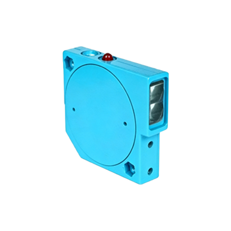
Connect the sensor’s power wires: typically brown for +24V DC and blue for 0V DC (ground). Use a regulated 24V DC power supply, ensuring the total current draw does not exceed the supply rating. For long cable runs, consider using twisted-pair shielded cable to reduce electrical noise. The shield should be grounded only at one end, usually at the power supply ground, to prevent ground loops.
Connecting the Sensor Output to the Servo Drive Input
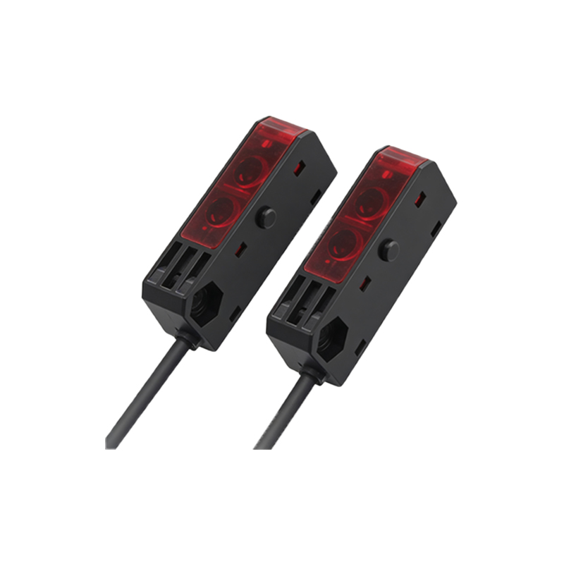
For a PNP sensor, connect its output wire (usually black) to the servo drive’s digital input terminal (e.g., DI1). For an NPN sensor, connect the output to the drive’s common input (COM) terminal, and then connect the sensor’s ground to the drive’s 0V. Ensure the drive’s input is configured in the software for the correct logic (e.g., active high or active low). Use a pull-up or pull-down resistor if specified by the drive manual to avoid floating signals.
Integrating the Sensor with the Servo Controller via PLC
If the sensor signal must be processed by a PLC before reaching the servo drive, wire the sensor output to the PLC’s digital input module. Then, program the PLC to send a trigger signal to the servo drive’s start or homing input. Use optocouplers or relays to isolate the PLC and drive if they share different voltage levels. Verify the PLC’s scan cycle time to ensure it does not introduce unacceptable delays in the servo response.
Testing and Troubleshooting the Wiring
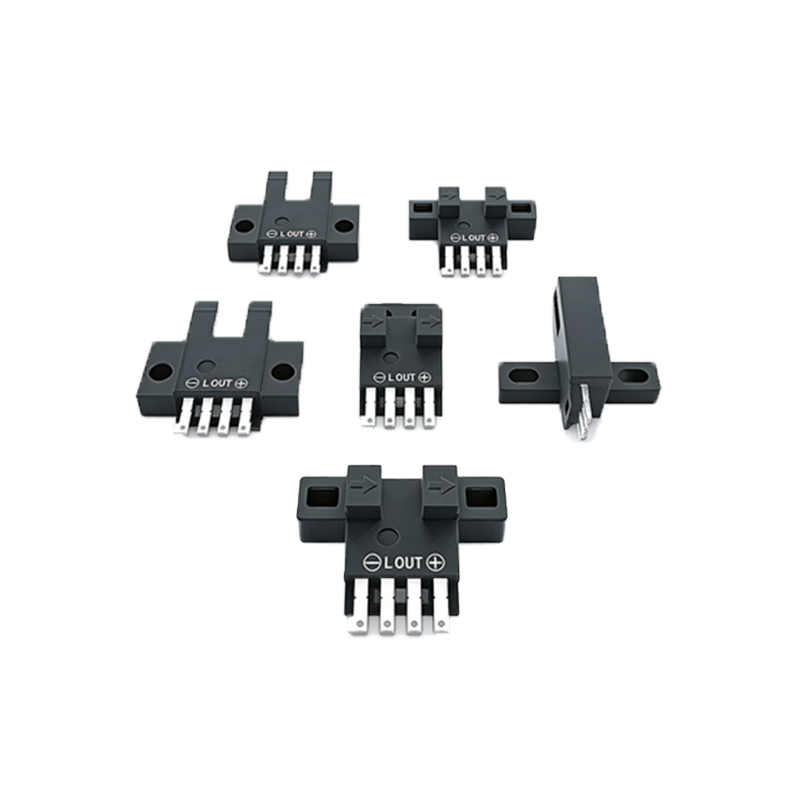
After wiring, power on the system and use a multimeter to measure the sensor’s output voltage. With the sensor activated, the output should be close to 24V (for PNP) or 0V (for NPN). Check the servo drive’s input status through its software interface. If the sensor signal is not detected, check for loose connections, incorrect polarity, or damaged cables. Add a ferrite bead or a noise filter on the sensor cable if the drive shows erratic behavior.
Safety Considerations and Best Practices
Always disconnect power before making any wiring changes. Use proper wire gauge (typically 22-18 AWG) to handle the current. Label all wires and terminals for future maintenance. For high-speed applications (e.g., sorting on a conveyor), choose a photoelectric sensor with a fast response time (under 1 ms) to avoid missed triggers. Ensure all ground connections are star-configured to minimize ground loops.