Introduction to Fiber Optic Photoelectric Sensors
Fiber optic photoelectric sensors represent a critical evolution in industrial sensing technology, leveraging light transmission through flexible optical fibers to detect objects, measure distances, and monitor processes in harsh environments. Unlike traditional photoelectric sensors that rely on direct line-of-sight light beams, these sensors separate the light source and receiver from the sensing head, enabling installation in confined spaces or areas with extreme temperatures, vibrations, or electromagnetic interference. As an electrical engineer specializing in industrial automation, I have observed their growing adoption in sectors like automotive manufacturing, semiconductor fabrication, and food processing.
Operating Principle and Key Components
The core operation of a fiber optic photoelectric sensor involves a transmitter that emits light, typically from an LED or laser diode, through a fiber optic cable to a sensing tip. The light then interacts with the target object—being reflected, blocked, or transmitted—and returns via the same or a separate fiber to a receiver, such as a photodiode. The sensor’s electronics interpret the light intensity change to generate a binary or analog output. Key components include the amplifier unit (housing the emitter and receiver), fiber optic cables (available in glass or plastic), and interchangeable sensing heads (through-beam, diffuse, or retro-reflective types). Glass fibers excel in high-temperature applications up to 300°C, while plastic fibers offer cost-effective solutions for standard environments.
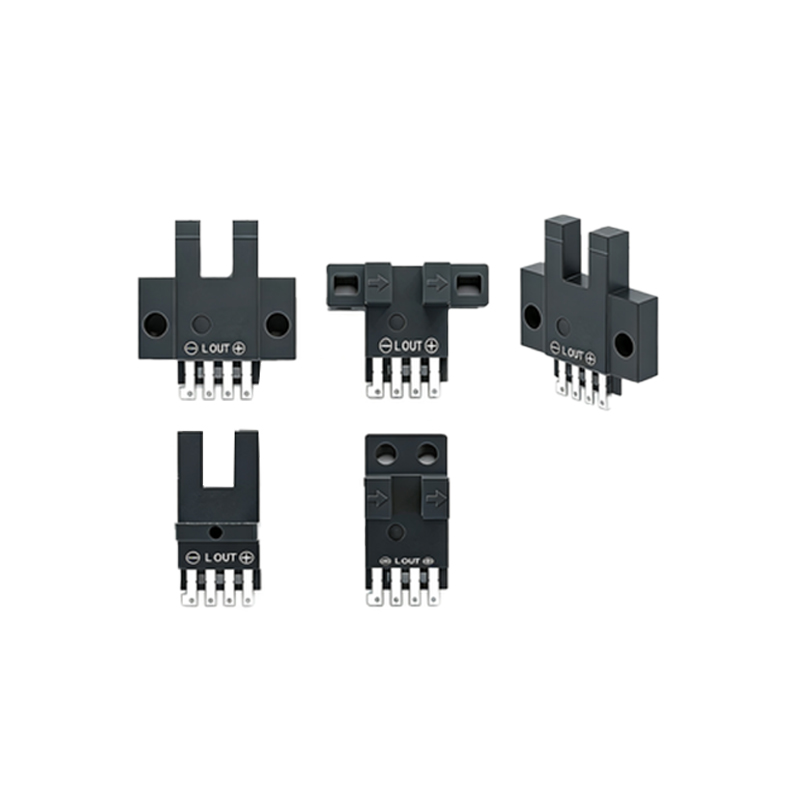
Advantages Over Conventional Sensors
Fiber optic sensors overcome several limitations of traditional photoelectric models. Their immunity to electromagnetic interference (EMI) makes them ideal for use near welding equipment, motors, or high-voltage lines. The ability to place the amplifier remotely from the sensing point allows operation in extreme temperatures—from -40°C to 250°C or higher with specialized cables. Additionally, their compact sensing tips can fit into gaps as small as 3 mm, beneficial for detecting small components in PCB assembly lines. Enhanced precision, with response times as low as 0.1 milliseconds, ensures reliable counting at high conveyor speeds.
Selection Criteria for Industrial Applications
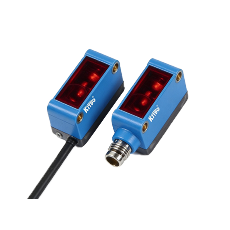
When selecting a fiber optic photoelectric sensor, engineers must evaluate several parameters: fiber type (glass for durability, plastic for flexibility), sensing distance (typically 0.1 mm to 15 m depending on configuration), output type (NPN, PNP, analog, or IO-Link), and ambient conditions. For example, in a dusty automotive paint shop, a through-beam configuration with glass fibers and air purge collars prevents lens contamination. For liquid level detection in chemical tanks, diffuse reflective sensors using fluoropolymer-coated fibers resist corrosion. Always match the sensor’s wavelength (e.g., 660 nm red light for general use, 940 nm infrared for invisible detection) to the target material’s reflectivity.
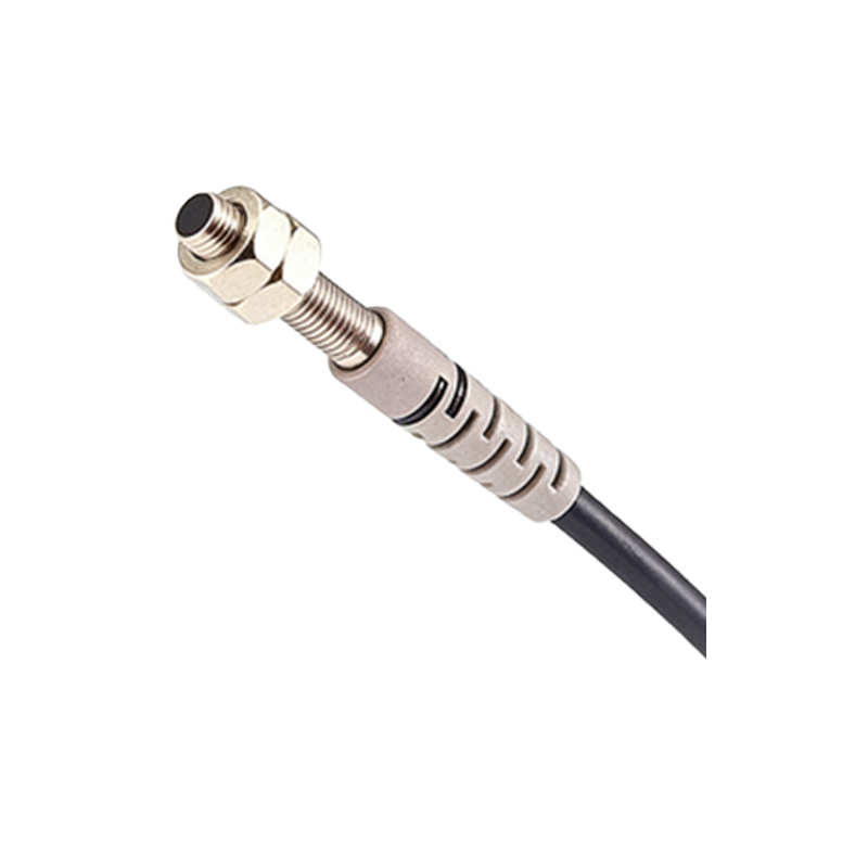
Integration and Calibration Best Practices
Proper integration begins with mounting the amplifier unit in a clean, accessible location, away from heat sources. Use fiber cleaving tools to ensure clean cuts on plastic fibers for optimal light transmission. Calibration involves setting the sensitivity threshold using the teach button or potentiometer—typically adjusting until the output switches reliably between the presence and absence of the target. For dynamic applications, enable the “dynamic teach” feature to auto-adjust for gradual changes like lens fogging. Always test with actual production materials and speeds to confirm margin stability. Regular inspection of fiber tips for scratches or contaminants extends service life.
Common Faults and Troubleshooting Techniques
Despite their robustness, fiber optic sensors can fail. A frequent issue is signal loss due to broken fibers or loose connectors—verify continuity with a visual fault locator (red laser). If the sensor shows false triggers, check for ambient light interference (e.g., from welding arcs) using a hooded sensing tip or by switching to modulated light. Inconsistent detection may result from fiber bending beyond the minimum radius (typically 25 mm for glass), causing micro-cracks. Replace damaged sections or use bend-insensitive fibers. For amplifier errors, reset the device by cycling power, then recalibrate.
Future Trends and Industry Outlook
The future of fiber optic photoelectric sensors lies in greater intelligence and connectivity. Emerging models integrate IO-Link communication for real-time diagnostics, parameter changes, and predictive maintenance alerts. Miniaturization continues, with amplifiers now available in DIN-rail modules smaller than a credit card. Multi-wavelength sensors are being developed to differentiate materials by color or opacity, expanding applications in sorting and quality control. As Industry 4.0 demands higher reliability and data integration, these sensors will become even more indispensable in smart factories.