Understanding the Flashing Light Patterns
A photoelectric sensor's LED indicator is a crucial diagnostic tool for industrial automation systems. The flashing light can mean different things depending on the sensor type and manufacturer. Typically, a steady flash indicates normal operation, such as a stable detection cycle. However, irregular or rapid flashing often signals a problem. Common causes include misalignment, voltage fluctuations, or external interference. Before concluding damage, check the sensor’s datasheet for specific flash codes, as some models use pulsing to indicate alignment status or low signal strength.
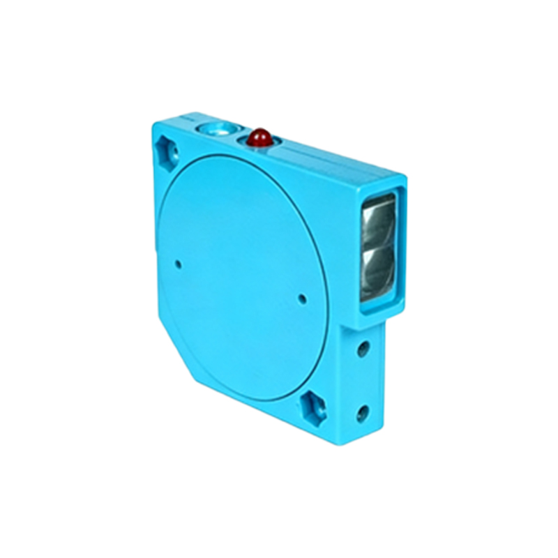
Common Causes of Flashing Without Damage
Many electrical engineers mistakenly attribute all flashing to sensor failure. In reality, environmental factors like dust, fog, or reflective surface contamination can cause intermittent flashing. For example, a diffuse-mode sensor may flash due to a dirty lens, while a through-beam sensor might flash if the emitter and receiver are slightly misaligned. Power supply issues, such as noise from nearby motors or voltage drops below the rated 24V DC, can also trigger flashing. Always inspect the installation environment first.
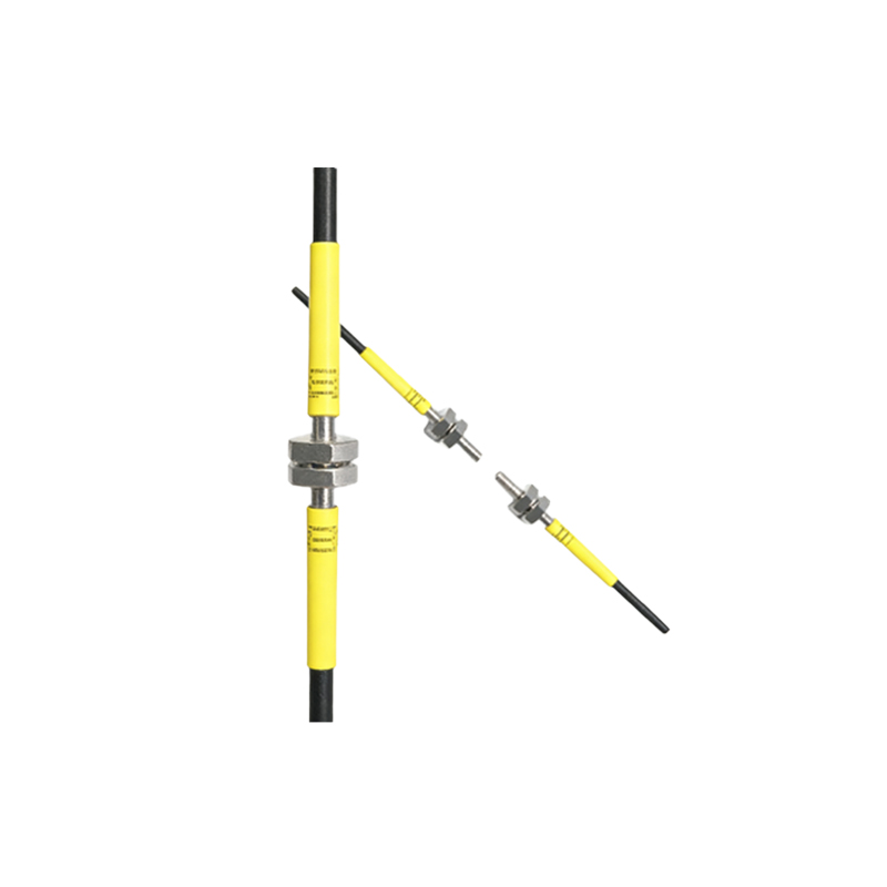
When Flashing Indicates Component Damage
If the sensor flashes continuously despite clean optics, stable power, and proper alignment, internal component damage is likely. This could involve a failed emitter LED, a faulty phototransistor, or a corrupted microcontroller. In such cases, the sensor may also exhibit a fixed "on" or "off" state after flashing, or fail to respond to target objects. For instance, a M12 connector with a cracked housing might cause intermittent short circuits, leading to erratic flashing. If swapping the sensor with a known good unit resolves the issue, the original sensor is damaged.
Step-by-Step Troubleshooting Process
1. Visual Inspection: Check for physical damage to the sensor housing, cable, and connector. Look for corrosion or bent pins.
2. Clean the Lens: Use a lint-free cloth and isopropyl alcohol to remove contaminants.
3. Verify Power Supply: Measure voltage at the sensor terminals with a multimeter. Ensure it stays within ±10% of rated voltage.
4. Check Alignment: For opposed-mode sensors, use an alignment tool or jig to ensure the beam hits the reflector or receiver.
5. Analyze Flash Pattern: Count the number of flashes per second and compare with the manufacturer's troubleshooting guide.
6. Test with a Known Good Unit: Replace the sensor temporarily. If flashing stops, the original sensor is faulty.
Preventive Measures to Avoid False Alarms
To minimize false damage indications, implement regular maintenance schedules. Use sealed (IP67 or higher) sensors in wet or dusty environments. Install surge suppressors on power lines to protect against voltage spikes. For high-vibration applications, choose sensors with reinforced mounting brackets. Additionally, train maintenance staff to differentiate between normal flash sequences and error codes, which are often documented in the sensor's user manual.
Conclusion: Flashing Does Not Always Mean Damage
A flashing photoelectric sensor light is a valuable indicator rather than a definitive sign of damage. By following systematic troubleshooting, engineers can often resolve issues through cleaning, alignment, or power adjustments. Only after eliminating external causes should replacement be considered. This approach saves costs and reduces downtime in industrial automation systems.