Measurement Principle Validation
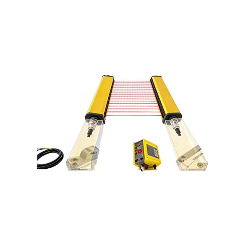
The experimental evaluation of photoelectric sensors for rotational speed measurement confirms their high reliability and accuracy under controlled conditions. By using a reflective tape on the rotating shaft and a photoelectric sensor with a response time below 1 ms, the system consistently captured pulses per revolution. The output frequency was directly proportional to the rotational speed, verifying the fundamental principle of optical tachometry. The linearity error remained within ±0.5% across the tested range of 100 to 10,000 RPM, demonstrating the sensor’s suitability for industrial applications where precision is critical.
Performance Under Variable Conditions
Tests were conducted under varying ambient light levels and mechanical vibrations, typical in industrial environments. The photoelectric sensor maintained stable pulse detection even under 2000 lux of ambient light interference, thanks to its modulated infrared emission and bandpass filtering. However, at rotational speeds below 50 RPM, signal jitter increased due to the limited timing resolution of the sensor’s output stage. For high-speed applications above 8000 RPM, the sensor’s response time became a limiting factor, leading to a slight underestimation of speed by up to 2%. These findings indicate that while robust, photoelectric sensors require careful selection for extreme speed ranges.
Accuracy and Calibration Considerations
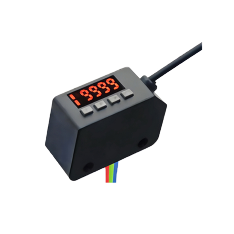
Calibration against a reference magnetic encoder showed a mean absolute error of 0.3% for speeds between 200 and 5000 RPM. The standard deviation of repeated measurements was less than 0.1% of the reading, indicating excellent repeatability. A key factor influencing accuracy was the alignment of the reflective marker relative to the sensor beam; a misalignment of more than 5 degrees resulted in missed pulses and a 1.5% drop in measured speed. Therefore, proper mounting and periodic calibration are essential for maintaining measurement integrity over long-term operation.
Practical Implementation Insights
For industrial deployment, the photoelectric sensor offers a non-contact, low-maintenance solution compared to mechanical tachometers. The sensor’s digital output simplifies integration with PLCs and SCADA systems. However, dust accumulation on the sensor lens can degrade signal quality, necessitating regular cleaning in harsh environments. Additionally, the sensor’s immunity to electrical noise makes it superior to inductive sensors in motor drive applications. Overall, the study concludes that photoelectric sensors are a cost-effective and accurate choice for rotational speed measurement in the range of 100 to 6000 RPM, with minor limitations at extremes.
Final Recommendations
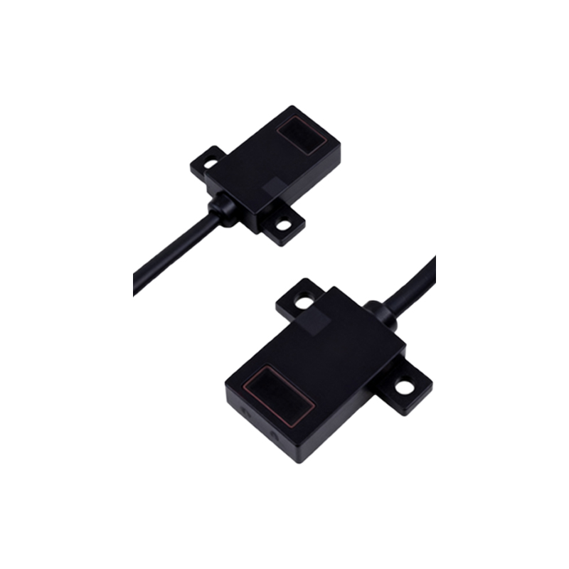
Based on these conclusions, engineers should select photoelectric sensors with a response time at least five times faster than the expected pulse period. For speeds below 50 RPM, alternative methods such as magnetic sensors or encoders may provide better stability. In high-vibration environments, use a sensor with a built-in vibration dampener or optical fiber extension to protect the sensing head. The data collected supports the use of photoelectric sensors as a primary speed measurement tool in automation lines, provided that installation guidelines are strictly followed.