Introduction to Rotary Photoelectric Sensors
Rotary photoelectric sensors, also known as optical encoders, are critical components in industrial automation, robotics, and precision motion control systems. These sensors convert mechanical rotation into electrical signals, enabling accurate position, speed, and direction measurement. Understanding their circuit diagram is essential for engineers designing feedback loops or troubleshooting existing systems. This article provides a detailed, industry-focused analysis of the typical circuit structure, key components, and practical design considerations.
Basic Operating Principle of Rotary Photoelectric Sensors
A rotary photoelectric sensor fundamentally consists of a light source (usually an LED), a rotating disk with patterned slits or reflective segments, and a photodetector (such as a photodiode or phototransistor). As the disk rotates, it alternately blocks and transmits light, generating a series of pulses. The circuit diagram for such a sensor typically includes three main blocks: the emitter circuit, the detector circuit, and the signal conditioning circuit. The emitter circuit drives the LED with a constant current to ensure stable light output, while the detector circuit converts the modulated light into a weak current signal. Proper biasing and filtering in these stages are crucial for noise immunity.
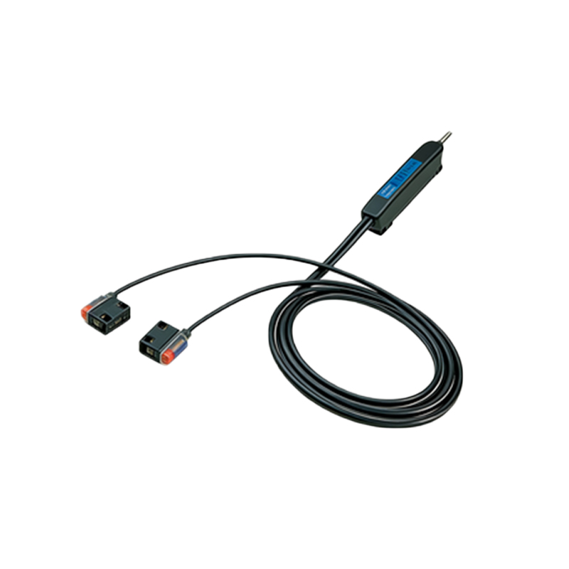
Key Components in the Circuit Diagram
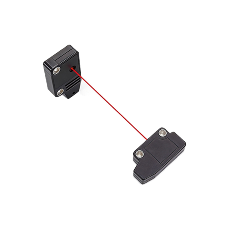
The circuit diagram for a typical rotary photoelectric sensor (e.g., an incremental encoder) includes several standard components:
- LED and current-limiting resistor: Provides a stable light source. The resistor value is calculated based on the LED's forward voltage and desired current (typically 10-20 mA).
- Phototransistor or photodiode: Acts as the optical receiver. A phototransistor offers higher gain but slower response, while a photodiode requires a transimpedance amplifier for signal conversion.
- Comparator or Schmitt trigger: Converts the analog photodetector signal into a clean digital pulse train. This stage eliminates noise and provides hysteresis to prevent false triggering.
- Pull-up resistors and decoupling capacitors: Ensure stable voltage levels and filter high-frequency noise from the power supply.
Engineers must pay special attention to component selection: for high-speed applications, a photodiode with a bandwidth above 1 MHz is preferred, while for low-speed, high-noise environments, a phototransistor with integrated base resistor may be more robust.
Signal Conditioning and Output Stage
The raw signal from the photodetector is often weak and noisy, requiring amplification and shaping. The circuit typically uses an operational amplifier (op-amp) in a transimpedance configuration for photodiode inputs, converting the current to a voltage. For phototransistors, a simple voltage divider with a collector resistor suffices. After amplification, a comparator (e.g., LM393) with adjustable threshold and hysteresis generates a square-wave output. The output stage may include a line driver (e.g., RS-422) for long-distance transmission or an open-collector output for direct connection to a PLC or microcontroller. A practical circuit diagram should also include protection diodes to prevent reverse polarity and ESD damage.
Practical Design Considerations and Troubleshooting
When designing or analyzing a rotary photoelectric sensor circuit, engineers must consider several factors:
- Optical alignment: Misalignment between the LED and detector can cause signal dropout. Use mechanical fixtures or optical lenses to focus the beam.
- Operating temperature: LED and photodetector characteristics drift with temperature. Include compensation circuits or select components with wide temperature ranges (e.g., -40°C to +85°C).
- Power supply noise: Use a linear regulator and ferrite beads to filter ripple from industrial power lines.
- Testing and validation: Use an oscilloscope to check the output waveform at maximum rotation speed. Look for clean transitions with less than 10% duty cycle distortion. Common faults include dead zones (due to dust on the disk) and pulse jitter (caused by mechanical vibration or electrical interference). Always verify the circuit against the sensor's datasheet specifications, such as maximum frequency response and output logic levels.
Conclusion: Integrating the Circuit into Systems
Mastering the circuit diagram of a rotary photoelectric sensor is fundamental for any electrical engineer working in motion control or industrial automation. The design must balance cost, speed, and reliability, with careful attention to component selection and signal integrity. By following the guidelines in this article, engineers can create robust circuits that deliver accurate feedback for applications ranging from servo motors to conveyor belt speed monitoring. Always refer to the latest industry standards (e.g., IEC 61131-2) for compliance and document your design thoroughly for future maintenance.