Introduction to EIS Optical Sensors in Mercedes-Benz
The Electronic Ignition System (EIS) in modern Mercedes-Benz vehicles relies on advanced optical sensors to ensure precise engine timing and fuel injection. As an automotive electrical engineer, understanding the working principle of these optical sensors is critical for diagnostics and troubleshooting. Unlike traditional Hall-effect sensors, EIS optical sensors use light-based detection to monitor crankshaft and camshaft positions, offering higher accuracy and faster response times in high-performance applications.
Core Components of the EIS Optical Sensor
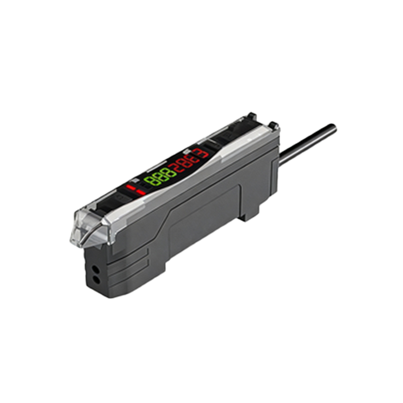
The EIS optical sensor consists of three primary components: a light-emitting diode (LED), a photodetector (such as a photodiode or phototransistor), and a rotating encoder disk with slits. The encoder disk is mechanically coupled to the engine crankshaft or camshaft. The LED emits a focused beam of infrared or visible light toward the photodetector. The slits on the disk modulate this light beam as the shaft rotates, creating a series of optical pulses. These pulses are then converted into electrical signals for the Engine Control Unit (ECU).
Principle of Light Modulation: Slit-Based Encoding
The encoder disk features a precise pattern of slots or reflective surfaces. In a typical slotted design, the disk interrupts the light beam as it rotates. When a slit aligns with the LED and photodetector, light passes through, generating a high signal; when a solid section blocks the light, the signal drops to low. This on-off pattern creates a square wave signal. Mercedes-Benz uses high-resolution disks with multiple slits to achieve accurate angular position detection down to fractions of a degree. The signal frequency is directly proportional to the rotational speed, enabling the ECU to calculate RPM and ignition timing.
Signal Processing and Output to ECU
The raw optical signal from the photodetector is weak and noisy, so it undergoes amplification and conditioning within the sensor module. A comparator circuit converts the analog light intensity into a clean digital square wave. This digital signal is then transmitted to the ECU via a shielded twisted-pair cable to minimize electromagnetic interference (EMI). The ECU uses this signal, along with data from other sensors, to determine the optimal ignition timing, fuel injection duration, and variable valve timing. For Mercedes-Benz models with direct fuel injection, the optical sensor must provide a signal with jitter less than 0.1 degrees of crankshaft rotation.
Advantages Over Magnetic Sensors
Optical sensors in the EIS offer several advantages over traditional magnetic pickups. They are immune to magnetic interference from starter motors and alternators, which is common in Mercedes-Benz hybrid systems. Additionally, optical sensors can detect direction of rotation by using two photodetectors with a phase shift, enabling the ECU to identify engine reverse rotation during start-stop events. However, optical sensors require a clean environment, as oil or dirt on the encoder disk can degrade performance. Regular maintenance of the sensor window is recommended.
Common Failure Modes and Diagnostic Tips
When diagnosing EIS optical sensor issues in Mercedes-Benz vehicles, common symptoms include erratic idle, misfires, or no-start conditions. A failed LED will produce no output, while a misaligned encoder disk causes intermittent signals. Using an oscilloscope, you can measure the sensor output waveform. A healthy signal should show clean square waves with consistent amplitude and frequency. If the waveform is distorted or has missing pulses, inspect the sensor for contamination or mechanical damage. In some models, the sensor may require recalibration after replacement using the Mercedes-Benz diagnostic scan tool.