Introduction to Photoelectric Sensors and Output Types
In industrial automation, photoelectric sensors are widely used to detect the presence or absence of objects, distances, or changes in material properties. These sensors operate by emitting a light beam, usually infrared or visible, and measuring the reflected or interrupted light. One critical aspect of their configuration is the output type, which dictates how the sensor interfaces with controllers, PLCs, or other devices. Among common output types, PNP and NPN are the most prevalent, particularly in DC-powered systems. As an electrical engineer, I often encounter confusion among technicians and designers regarding the practical meaning of PNP. This article clarifies what PNP means in the context of photoelectric sensors and why it matters for wiring and troubleshooting.
What Does PNP Stand For in Electronics?
PNP is an acronym derived from the structure of a transistor: Positive-Negative-Positive. This refers to the semiconductor layers used in bipolar junction transistors (BJTs). In a PNP transistor, current flows from the emitter (P-type) to the collector (P-type) when a negative voltage is applied to the base (N-type). When applied to photoelectric sensors, the term PNP indicates that the sensor's output stage uses a PNP transistor as a switching element. Essentially, this means the sensor acts as a current source. When activated, it connects the output line to the positive supply voltage (V+ or +24V DC), sourcing current to the load. This contrasts with NPN outputs, which sink current to ground. Understanding this fundamental difference is crucial for selecting the correct sensor type for a given input card or relay.
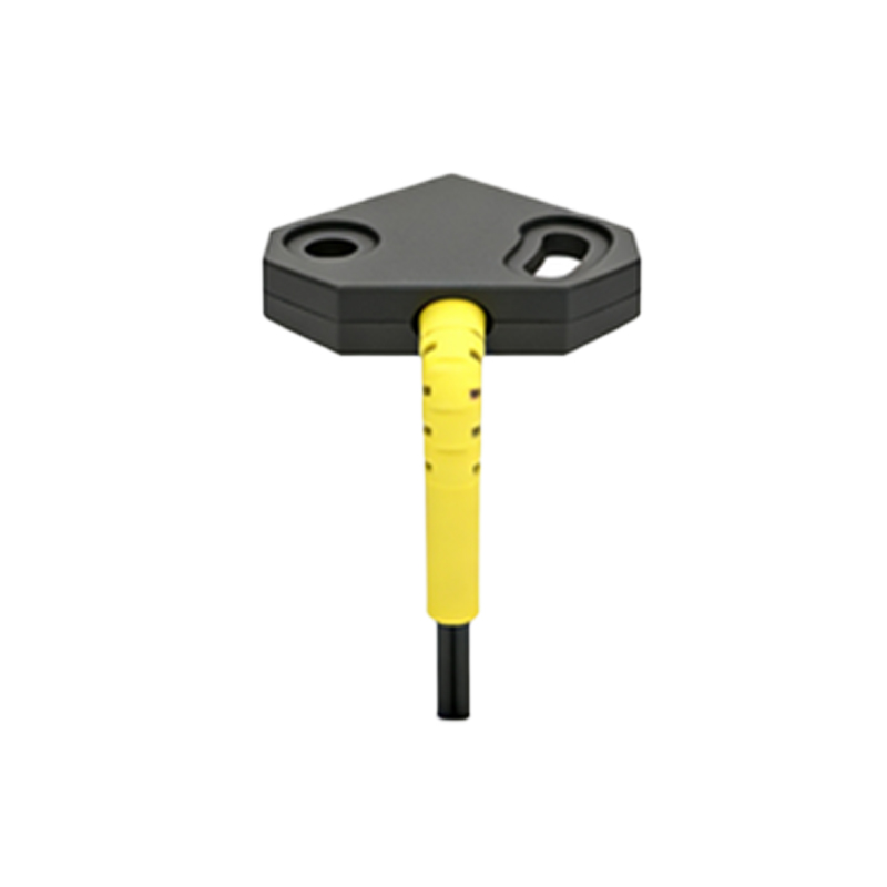
How a PNP Photoelectric Sensor Works
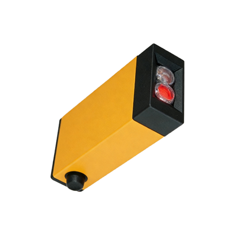
A PNP photoelectric sensor typically has three wires: brown (positive supply, typically +24V DC), blue (negative supply, 0V or ground), and black (output signal). Internally, the sensor’s photodetector circuitry triggers the base of the PNP transistor when an object is detected. When the transistor turns on, it allows current to flow from the power supply through the collector and emitter, effectively connecting the black wire to the brown wire. Consequently, the output voltage rises to near the supply voltage (e.g., +24V) during an active detection event. When no object is present, the transistor turns off, and the output is pulled low by a resistor, typically close to 0V. This high-side switching behavior makes PNP sensors ideal for systems where the load (such as a PLC input) needs to see a positive voltage for activation.
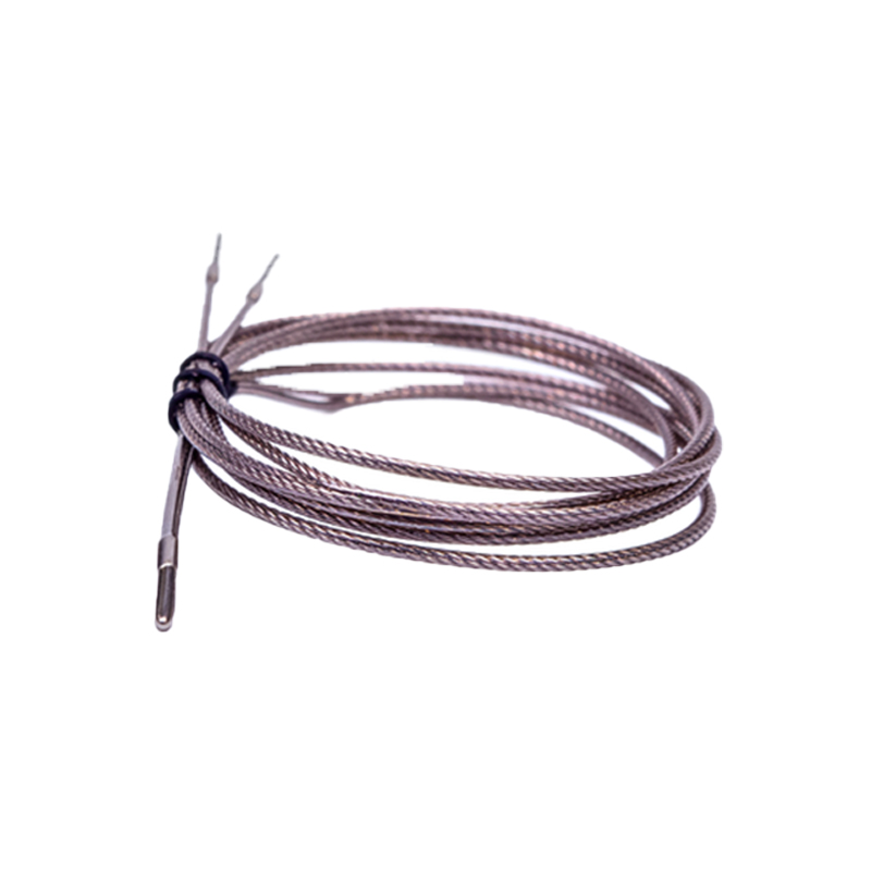
Wiring Considerations for PNP Sensors
When integrating a PNP photoelectric sensor into a control system, proper wiring is vital to prevent damage and ensure reliable operation. The brown wire must connect to the positive terminal of the power supply, and the blue wire to the negative terminal (ground). The black output wire should be connected to the input of the receiving device, such as a PLC digital input module. It is important to verify that the input module is compatible with PNP outputs. For a typical sourcing input, the module should be configured for “sourcing” or “positive logic,” meaning it expects a high voltage (above a threshold, often >15V for 24V systems) to register a logic high. If the input module is designed for NPN (sinking) signals, a PNP sensor will not work directly without additional circuitry like a resistor pull-down or a signal converter. Always consult the device datasheet to confirm voltage ratings and current limits.
Advantages of PNP Sensors in Industry
PNP sensors are preferred in many industrial settings, especially in European and Asian markets, due to their perceived safety and ease of troubleshooting. For instance, since the output is high (positive voltage) when active, it is less susceptible to false triggering from stray ground currents or interference. Additionally, in the event of a short circuit to ground, the PNP output typically does not cause a direct power supply fault, as the transistor is normally off. This makes them suitable for applications where long cable runs or high electrical noise exists. Moreover, many modern PLCs and controllers are designed with PNP-compatible inputs, simplifying system integration. From a maintenance perspective, technicians can quickly verify a PNP sensor’s operation by measuring voltage between the black and blue wires: it should show approximately the supply voltage when triggered.
Common Misconceptions and Troubleshooting Tips
One common misconception is that PNP sensors can be interchanged with NPN sensors without any changes. This is false; swapping them often leads to no detection or damage to the input module. Always check the wiring diagram and the input module type before installation. Another issue is assuming the sensor output is always 24V when active; some sensors have voltage drops of 1-2V, which may be insufficient for older PLCs with high input thresholds. For troubleshooting, if a PNP sensor fails to trigger, first verify the power supply voltage between brown and blue (should be within spec, e.g., 10-30V DC). Then, measure the output voltage between black and blue under detection; it should be near the supply voltage. If it remains low, the sensor may be faulty, or the load might be drawing too much current beyond the sensor’s rated output (typically 100-200 mA). Always refer to the manufacturer’s data sheet for exact specifications.
Conclusion: When to Choose PNP Photoelectric Sensors
Choosing between PNP and NPN depends on the control system architecture. For new installations or systems with sourcing-input PLCs, PNP is often the standard choice due to its robustness against ground noise and common industry practices. Understanding that PNP stands for a positive output (source) is the key to correct wiring and integration. As an engineer, I recommend always labeling sensor wires and simulating the detection process during commissioning to validate the logic. With this knowledge, you can confidently select and troubleshoot PNP photoelectric sensors, ensuring reliable automation performance in harsh industrial environments.