Understanding Weak Signal Issues in Photoelectric Sensors
Photoelectric sensors are widely used in industrial automation for detecting objects, distances, and presence. However, a common challenge faced by engineers is weak signal output, which can lead to false readings, downtime, or reduced system reliability. When the signal strength drops below the threshold, the sensor may fail to trigger correctly, affecting process control. This article explores the root causes of weak signals and provides practical solutions for optimizing performance in demanding environments.
Common Causes of Weak Signal in Photoelectric Sensors
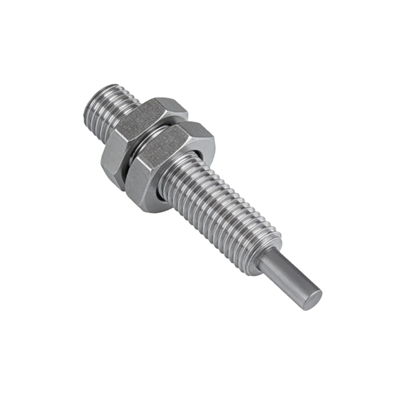
Weak signal can result from several factors, including optical contamination, misalignment, and environmental interference. Dust, oil, or condensation on the sensor lens or reflector reduces light transmission, directly attenuating the signal. Misalignment between the emitter and receiver, especially in through-beam or retro-reflective sensors, causes partial beam interruption. Additionally, ambient light sources, such as sunlight or nearby LED fixtures, can introduce noise or saturate the receiver. Distance and target reflectivity also play a role: dark or matte surfaces absorb more light, while long distances exceed the sensor’s detection range, weakening the return signal.
Diagnosing Signal Weakness with Proper Tools
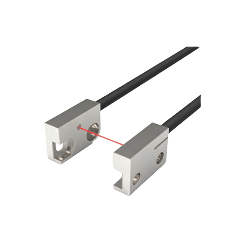
Engineers should first verify the sensor’s specifications, including operating distance, excess gain, and response time. Use a digital multimeter or oscilloscope to measure the output signal voltage or current under actual operating conditions. Check alignment by observing the indicator LED: a flickering or dim light often suggests misalignment or contamination. Test with a known reflective target to isolate sensor performance from target variations. Environmental factors, such as vibration or temperature fluctuations, can also degrade signals; thermal expansion may shift alignment in high-heat environments.
Solutions to Improve Signal Strength
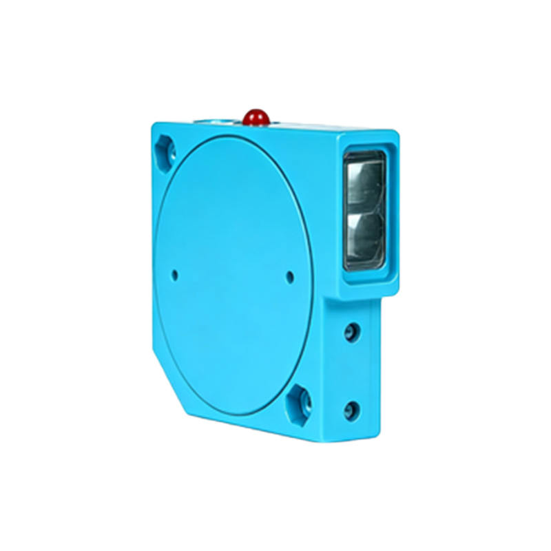
1. Clean and maintain optics: Regularly wipe sensor lenses and reflectors with lint-free cloths and approved solvents. For harsh environments, consider air-purging systems or protective housings.
2. Optimize alignment: Use laser alignment tools or bracket adjustments to ensure precise optical path. Retro-reflective sensors benefit from polarized filters to reduce false signals from shiny objects.
3. Adjust sensitivity and gain: Many sensors have potentiometers or software settings for adjusting threshold levels. Increase gain cautiously to avoid noise amplification, or reduce it to filter out background interference.
4. Select appropriate sensor type: For long distances or dusty conditions, fiber-optic or laser-based sensors offer higher signal stability. Background suppression sensors reject distant objects, improving reliability.
5. Shield from ambient light: Install physical guards or hoods to block direct sunlight. For indoor use, choose sensors with modulated infrared or visible red light to reject DC ambient interference.
Preventive Maintenance and System Design Tips
Integrate regular signal testing into preventive maintenance schedules. Monitor signal margins via digital outputs or PLC alarms to detect degradation early. In initial system design, allow 20-30% excess gain beyond the minimum requirement to accommodate aging or contamination. Use shielded cables and proper grounding to minimize electrical noise. For critical applications, implement redundant sensors or fail-safe logic to handle weak signals gracefully. By combining technical diagnostics with proactive design, engineers can significantly reduce weak-signal-related failures.